Translate this page into:
An anatomical evaluation of the mandibular buccal shelf: A cone beam computed tomography study

*Corresponding author: Rockey Shrivastava, Department of Orthodontics and Dentofacial Orthopaedics, Chitwan Medical College, Bharatpur, Nepal. shrivastavarockey@gmail.com
-
Received: ,
Accepted: ,
How to cite this article: Shrivastava R, Sah MP, Shrestha BK, Anjal GC, Gahatraj S. An anatomical evaluation of the mandibular buccal shelf: A cone beam computed tomography study. APOS Trends Orthod. doi: 10.25259/APOS_206_2024
Abstract
Objectives
The objectives of this article were to analyze the bone thickness and bone depth in the mandibular buccal shelf area at four sites, that is, a mesiobuccal section of mandibular first and second molar and distobuccal section of first and second molar and to analyze the bone thickness and bone height with respect to the spatial position of inferior alveolar nerve canal (IANC) at the right and left side and in males and females.
Material and Methods
Cone-beam computed tomography scans of 34 individuals were analyzed at four sites, that is, mesiobuccal section of the mandibular first and second molar and distobuccal section of first and second molar at both right and left sides and bone thickness as well as the bone depth of buccal shelf and IANC was measured and compared between right and left side and in between males and females.
Results
Bone thickness increased progressively in the distal direction. The highest bone depth was recorded in the distobuccal section of the second molar. IANC was also mapped and the result showed that the bone height from the cementoenamel junction (CEJ) to IANC decreased posteriorly but the bone depth was >18 mm at all sites. Very few parameters showed statistically significant differences between the right and left sides. Bone height to IANC from CEJ showed statistically significant differences between genders at a few sites with male subjects having higher values. Bone thickness in the IANC region showed no gender dimorphism.
Conclusion
The appropriate site for mandibular buccal shelf mini-implant placement is the distobuccal region of the mandibular second molar.
Keywords
Buccal shelf
Cone-beam computed tomography
Cementoenamel junction
Inferior alveolar nerve canal
Mini-implant

INTRODUCTION
Mini-implants are used in cases requiring absolute anchorage and are highly useful in orthodontic clinics. Although they are frequently placed at sites in between the roots of two contiguous teeth, new extra-alveolar sites have been suggested by Chang et al.,[1] Park et al.,[2] Almeida et al.,[3] and others. These authors recommended the placement of mini-implants in the area of the Infrazygomatic crest and buccal shelf region for an effective and secure anchorage system.
Anatomically, the buccal shelf region corresponds to the bone plateau that lies between the buccal aspect of the lower molars and the mandibular external oblique line. The plateau widens in the second and third molar regions. According to Chang et al.[4] and De Almeida,[5] the ideal area for the positioning of the mini-implants is in between the roots of the first and second lower molars both at an angle and perpendicular to the bone, which is almost parallel to the long axis of the molars due to adequate thickness of cortical bone and reasonable amount of attached gingiva in this region. However, the optimal insertion site in the buccal shelf region and variability that the vertical growth pattern, age, and sex induce remain unclear due to local anatomic variability.[4,6-8] In addition, understanding variation in position and course of the inferior alveolar nerve canal (IANC) is extremely important for mini-implant insertion in buccal shelf region to avoid perisurgical and postsurgical complications citing its proximity to the mini-implant.[9] This study aimed to analyze the buccal bone thickness, bone depth, and cortical bone depth of the mandibular buccal shelf to determine the most suitable sites of the buccal shelf for mini-implant insertion using cone-beam computed tomography (CBCT) in the Nepalese population.
MATERIAL AND METHODS
Ethical approval of this research was obtained from the Institutional Review Committee of Chitwan Medical College, Bharatpur, Nepal on October 13, 2023 (CMCIRC/080/081–025). This retrospective cross-sectional study evaluated 34 CBCT scans of patients who were referred to the Department of Oral Medicine, Diagnosis, and Radiology at Chitwan Medical College from November 2023 to April 2024. Convenience sampling was used.
The sample consisted of 34 Nepalese individuals with 17 males and 17 females with the age range between 18 and 35 years. The mean age was 26.82 ± 5.84 years. Exclusion criteria included individuals with previous orthodontic treatment; extraction of lower first or second molars; implants or pontics replacing the lower first or second molars; periodontal disease, history of orthognathic surgery, or presence of any genetic syndrome; evident asymmetries; and CBCT showing supernumerary teeth, impacted teeth, or any other pathology in the area of interest.
CBCT scans were taken with Planmeca ProMax 3D Classic scanner (Asentajankatu 6 FI-00880 Helsinki Finland) with the following acquisition parameters: 60–90 kV, 5 mA, 30 s acquisition time, and 0.5 mm focal spot, with a maximum volume of 15 × 10 × 8 cm. All scans were saved in digital imaging and communications in medicine (DICOM)format and were analyzed using Planmeca Romexis® software.
After proper orientation, buccal shelf bone height and width and relation to IANC were evaluated at 4 sites on each side, that is, buccal to the mesiobuccal cusp of mandibular first molar (6M), buccal to the distobuccal cusp of mandibular first molar (6D), and buccal to the mesiobuccal (7M) and distobuccal (7D) cusp of mandibular second molars. To assess the buccal bone thickness, a reference line was drawn from the cementoenamel junction (CEJ) tangentially to the buccal root surface, and measurements were made at 6 mm and 11 mm from a true horizontal line apical to the CEJ, starting from the tangent to the root surface to the most buccal point of the cortical bone, as shown in [Figure 1].[10] Bone height of the buccal shelf was assessed at 4 mm and 5 mm buccal to the CEJ using a true vertical line which intercepted the external cortex of the mandible at two points, as shown in [Figure 2]. The distance between them was determined as the length of the bone in the vertical direction.[10] The positioning of IANC was also evaluated, as shown in [Figure 3]. The bone height was the shortest distance between the line passing through the highest point of IANC and the CEJ. The bone width at IANC was the distance between the most buccal part of IANC to the end of the buccal cortex in a horizontal direction, as shown in [Figure 4].[11]
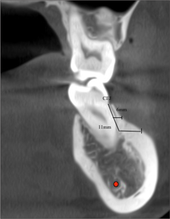
- Assessment of bone thickness at 6 mm and 11 mm from cementoenamel junction (CEJ). Red dot denotes Inferior alveolar nerve canal (IANC)

- Assessment of bone depth at 4 mm and 5 mm horizontal distance from cementoenamel junction (CEJ). Red dot denotes inferior alveolar nerve canal (IANC)
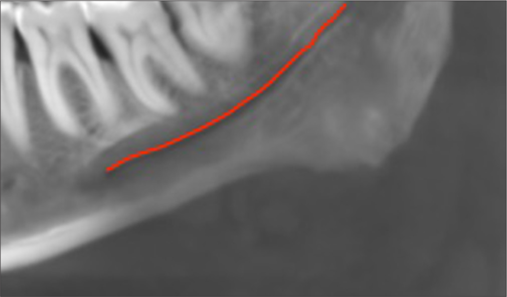
- Tracing of inferior alveolar nerve canal. Red line indicates Inferior alveolar nerve canal

- Assessment of bone thickness and bone height to the inferior alveolar nerve canal (IANC). CEJ: Cementoenamel junction. Red dot indicates inferior alveolar nerve canal (IANC)
RESULTS
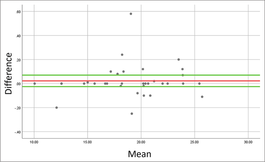
All the data were entered in Microsoft Excel software and later analyzed through the Statistical Package for the Social Sciences software version 25. The examiner repeated the measurements for each of the outcomes after 14 days and reliability was evaluated through the Intraclass Correlation Coefficient test. All the parameters showed excellent reliability ranging from 0.95 to 0.97. Bland Altman plots were also made to check the reliability of the measurements on the mesiobuccal root section of the first permanent molar on the right side. The Bland Altman plots are shown in Figures 5-10. The difference and the mean between the 2 measurements were represented in the y- and x-axis of the plots, respectively. There was no trend of proportional bias in all measurements. There were few outliers though but the regression coefficient showed no significant difference between mean bias and differences of all the stated measurements. Descriptive statistics for each parameter were measured. The normality of data distribution was measured using Kolmogorov–Smirnov test. Many parameters showed no normal distribution. Wilcoxon signed-rank test was used to compare all the parameters between the right and left sides of the samples. The gender-wise comparison was done using the Mann–Whitney U-test.
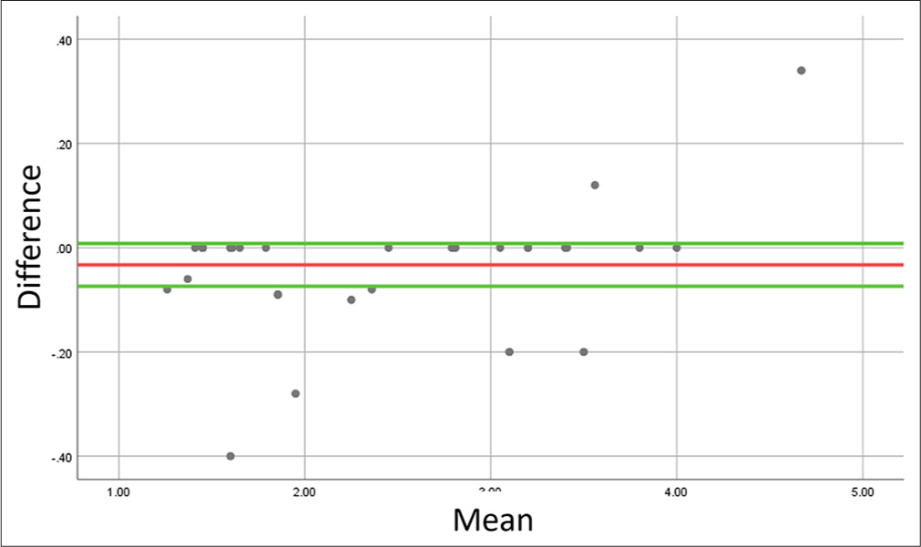
- Bland–Altman plot to evaluate agreement between repeated measurements of bone width at 6 mm distance from cementoenamel junction at the right mesiobuccal root of first molar. For each comparison, the bias is represented in red, whereas the positive and negative limits of agreement are represented in green lines.
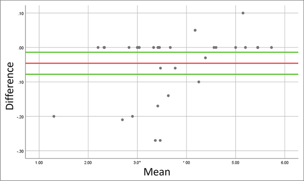
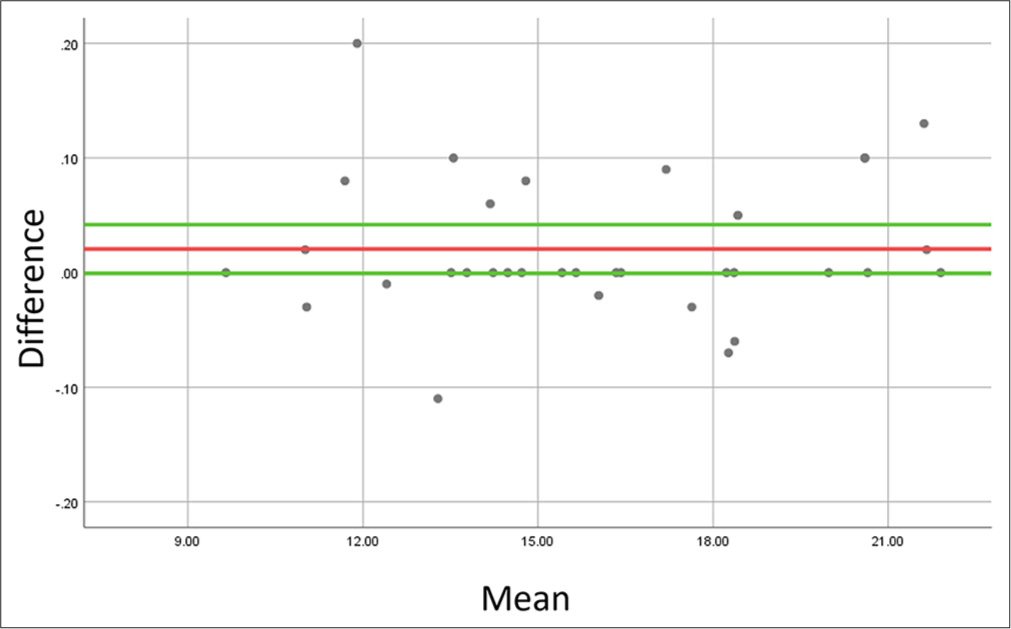
- Bland–Altman plot to evaluate agreement between repeated measurements of bone width at 11 mm distance from cementoenamel junction at the right mesiobuccal root of first molar. Bias is represented in red, whereas the positive and negative limits of agreement are represented in green lines.
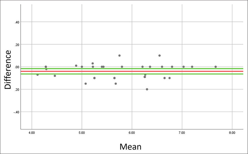
- Bland–Altman plot to evaluate agreement between repeated measurements of bone height at 4 mm distance from cementoenamel junction at the right mesiobuccal root of first molar. Bias is represented in red, whereas the positive and negative limits of agreement are represented in green lines.
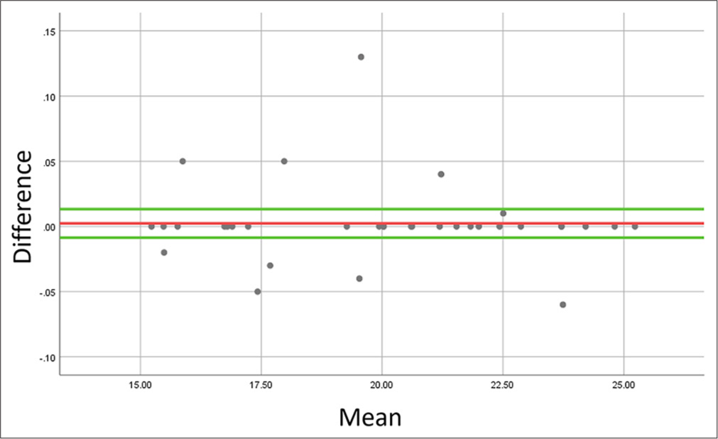
- Bland–Altman plot to evaluate agreement between repeated measurements of bone height at 5 mm distance from cementoenamel junction at the right mesiobuccal root of first molar. Bias is represented in red, whereas the positive and negative limits of agreement are represented in green lines.
- Bland–Altman plot to evaluate agreement between repeated measurements of bone width at inferior alveolar nerve canal at the right mesiobuccal root of first molar. Bias is represented in red, whereas the positive and negative limits of agreement are represented in green lines.
- Bland–Altman plot to evaluate agreement between repeated measurements of bone height at inferior alveolar nerve canal at the right mesiobuccal root of first molar. Bias is represented in red, whereas the positive and negative limits of agreement are represented in green lines.
[Table 1] shows the descriptive statistics and comparative measure of bone width at 6 mm and 11 mm from CEJ. It showed that bone width increased progressively at both right and left sides at 6 mm and 11 mm from CEJ in a posterior direction, that is, M6 < 6D < 7M < 7D. Table 1 also showed a statistically significant difference between the right and left sides at an 11 mm distance from CEJ at the sites 6M and 6D. [Table 2] shows descriptive and comparative statistics of bone height at 4 mm and 5 mm from CEJ. Table 2 also showed progressively increasing values in the distal direction. However, the difference between the right and left sides was statistically significant at two sites, that is, 6D at a 4 mm distance from CEJ and 7M at a 5 mm distance from CEJ. [Table 3] shows descriptive and comparative statistics of bone width and height of buccal shelf relative to IANC. The table 3 shows the highest bone height at the right side of 6M and the lowest at the left side of 7M and the difference was statistically significant right and left sides at 7M for bone height. The highest bone thickness at IANC was recorded at the right side of 7M and lowest at 6M and no statistically significant difference was noted between the right and left side for any of the values.
| Assessment point (mm) | Tooth/root (side) | Mean±SD (mm) | P-value |
|---|---|---|---|
| 6 | 6M (R) | 2.41±0.94 | 0.055 |
| 6M (L) | 2.73±0.86 | ||
| 6D (R) | 2.85±1.18 | 0.116 | |
| 6D (L) | 3.09±1.37 | ||
| 7M (R) | 5.11±2.29 | 0.592 | |
| 7M (L) | 5.01±1.91 | ||
| 7D (R) | 5.57±1.85 | 0.381 | |
| 7D (L) | 5.16±1.82 | ||
| 11 | 6M (R) | 3.69±1.09 | 0.000* |
| 6M (L) | 4.15±1.15 | ||
| 6D (R) | 4.26±1.10 | 0.000* | |
| 6D (L) | 4.44±1.34 | ||
| 7M (R) | 6.42±0.91 | 0.871 | |
| 7M (L) | 6.43±1.48 | ||
| 7D (R) | 6.71±2.02 | 0.180 | |
| 7D (L) | 5.98±1.54 |
Right, L: Left, SD: Standard deviation, P-value: Level of significance of Wilcoxon signed rank test, * Denotes statistically significant difference. CEJ: Cementoenamel junction
| Assessment Point (mm) | Tooth/root (side) | Mean±SD (mm) | P-value |
|---|---|---|---|
| 4 | 6M (R) | 19.02±3.87 | 0.675 |
| 6M (L) | 18.92±3.89 | ||
| 6D (R) | 19.73±2.92 | 0.000* | |
| 6D (L) | 19.28±2.82 | ||
| 7M (R) | 20.70±2.59 | 0.118 | |
| 7M (L) | 19.60±2.44 | ||
| 7D (R) | 20.84±2.60 | 0.731 | |
| 7D (L) | 20.96±2.01 | ||
| 5 | 6M (R) | 16.11±3.41 | 0.516 |
| 6M (L) | 15.85±3.52 | ||
| 6D (R) | 16.77±2.43 | 0.374 | |
| 6D (L) | 16.33±2.53 | ||
| 7M (R) | 18.03±2.69 | 0.010* | |
| 7M (L) | 16.82±2.60 | ||
| 7D (R) | 18.24±2.69 | 0.688 | |
| 7D (L) | 18.37±2.08 |
R: Right, L: Left, SD: Standard deviation, P-value: level of significance of Wilcoxon signed-rank test, * denotes statistically significant difference. CEJ: Cementoenamel junction
| Parameter | Tooth/root (side) | Mean±SD (mm) | P-value |
|---|---|---|---|
| Bone height | 6M (R) | 19.97±2.99 | 0.169 |
| 6M (L) | 19.35±3.13 | ||
| 6D (R) | 19.86±2.51 | 0.732 | |
| 6D (L) | 19.84±2.71 | ||
| 7M (R) | 19.00±2.53 | 0.017* | |
| 7M (L) | 18.10±2.43 | ||
| 7D (R) | 18.96±2.26 | 0.499 | |
| 7D (L) | 19.11±1.99 | ||
| Bone thickness | 6M (R) | 5.73±0.91 | 0.527 |
| 6M (L) | 5.61±0.97 | ||
| 6D (R) | 6.38±1.04 | 0.097 | |
| 6D (L) | 6.17±0.83 | ||
| 7M (R) | 6.79±1.21 | 0.242 | |
| 7M (L) | 6.49±1.16 | ||
| 7D (R) | 6.41±1.11 | 0.871 | |
| 7D (L) | 6.45±0.96 |
R: Right, L: Left, SD: Standard deviation, P-value: level of significance of Wilcoxon signed-rank test, * denotes statistically significant difference. IANC: Inferior alveolar nerve canal
[Table 4] shows gender-wise descriptive statistics and comparative measures of bone width at 6 mm and 11 mm from CEJ. It shows comparable parameters with no gender dimorphism. [Table 5] shows gender-wise descriptive and comparative statistics of bone height at 4 mm and 5 mm from CEJ and it shows a statistically significant difference between males and females at one site, that is, the left side of 7M at 5 mm from CEJ. [Table 6] shows the dimensions of the buccal shelf in relation to IANC. It shows a statistically significant difference between males and females for four sites for bone height with respect to IANC, that is, the left side of 6D, the right side of 7M, the right side of 7D, and the left side of 7D.
| Assessment Point (mm) | Tooth/root (side) | Mean±SD (mm) | Gender | P-value | |
|---|---|---|---|---|---|
| Male | Female | ||||
| 6 | 6M (R) | 2.41±0.94 | 2.54±1.00 | 2.27±0.90 | 0.433 |
| 6M (L) | 2.73±0.86 | 2.72±0.94 | 2.75±0.81 | 0.812 | |
| 6D (R) | 2.85±1.18 | 2.99±1.48 | 2.70±0.81 | 0.563 | |
| 6D (L) | 3.09±1.37 | 3.07±1.58 | 3.10±1.16 | 0.708 | |
| 7M (R) | 5.11±2.29 | 4.90±2.64 | 5.32±1.94 | 0.454 | |
| 7M (L) | 5.01±1.91 | 4.80±1.96 | 5.23±1.90 | 0.433 | |
| 7D (R) | 5.57±1.85 | 5.07±2.32 | 6.07±1.06 | 0.122 | |
| 7D (L) | 5.16±1.82 | 4.79±1.93 | 5.53±1.68 | 0.193 | |
| 11 | 6M (R) | 3.69±1.09 | 3.78±1.05 | 3.60±1.16 | 0.786 |
| 6M (L) | 4.15±1.15 | 4.19±1.34 | 4.12±0.97 | 0.734 | |
| 6D (R) | 4.26±1.10 | 4.38±1.33 | 4.14±0.82 | 0.610 | |
| 6D (L) | 4.44±1.34 | 4.23±1.25 | 4.65±1.44 | 0.540 | |
| 7M (R) | 6.42±0.91 | 6.61±2.57 | 6.60±2.87 | 0.454 | |
| 7M (L) | 6.43±1.48 | 6.26±1.57 | 6.60±1.42 | 0.474 | |
| 7D (R) | 6.71±2.02 | 6.54±2.34 | 6.88±1.68 | 0.394 | |
| 7D (L) | 5.98±1.54 | 5.83±1.53 | 6.13±1.57 | 0.322 | |
R: Right, L: Left, SD: Standard deviation, P-value: Level of significance of Mann–Whitney U-test. CEJ: Cementoenamel junction
| Assessment point (mm) | Tooth/root (side) | Mean±SD (mm) | Gender | P-value | |
|---|---|---|---|---|---|
| Male | Female | ||||
| 4 | 6M (R) | 19.02±3.87 | 19.22±3.56 | 18.82±4.25 | 0.586 |
| 6M (L) | 18.92±3.89 | 19.31±2.82 | 18.54±4.79 | 0.518 | |
| 6D (R) | 19.73±2.92 | 19.48±3.38 | 19.99±2.46 | 0.786 | |
| 6D (L) | 19.28±2.82 | 19.40±2.10 | 19.17±3.46 | 0.708 | |
| 7M (R) | 20.70±2.59 | 21.23±2.97 | 20.17±2.11 | 0.586 | |
| 7M (L) | 19.60±2.44 | 20.65±2.40 | 18.55±2.04 | 0.022* | |
| 7D (R) | 20.84±2.60 | 21.04±3.15 | 20.65±2.00 | 1.000 | |
| 7D (L) | 20.96±2.01 | 20.87±1.96 | 21.05±2.12 | 0.658 | |
| 5 | 6M (R) | 16.11±3.41 | 16.07±3.42 | 16.15±3.50 | 0.973 |
| 6M (L) | 15.85±3.52 | 15.84±2.27 | 15.85±4.52 | 0.610 | |
| 6D (R) | 16.77±2.43 | 16.65±2.74 | 16.88±2.15 | 0.563 | |
| 6D (L) | 16.33±2.53 | 16.37±1.79 | 16.29±3.16 | 0.496 | |
| 7M (R) | 18.03±2.69 | 18.25±3.25 | 17.82±2.05 | 0.865 | |
| 7M (L) | 16.82±2.60 | 17.57±2.50 | 16.07±2.56 | 0.670 | |
| 7D (R) | 18.24±2.69 | 18.44±2.99 | 18.04±2.42 | 0.586 | |
| 7D (L) | 18.37±2.08 | 18.23±1.75 | 18.52±2.41 | 0.683 | |
R: Right, L: Left, SD: Standard deviation, P-value: Level of significance of Mann–Whitney U-test, * denotes statistically significant difference. CEJ: Cementoenamel junction
| Parameter | Tooth/root (side) | Mean±SD (mm) | Gender | P-value | |
|---|---|---|---|---|---|
| Male | Female | ||||
| Bone height | 6M (R) | 19.97±2.99 | 20.60±2.94 | 19.34±3.00 | 0.259 |
| 6M (L) | 19.35±3.13 | 20.14±3.08 | 18.56±3.07 | 0.079 | |
| 6D (R) | 19.86±2.51 | 20.31±2.62 | 19.40±2.39 | 0.518 | |
| 6D (L) | 19.84±2.71 | 20.81±2.71 | 18.88±2.42 | 0.041* | |
| 7M (R) | 19.00±2.53 | 20.34±2.14 | 17.66±2.20 | 0.010* | |
| 7M (L) | 18.10±2.43 | 19.11±2.49 | 17.10±1.97 | 0.053 | |
| 7D (R) | 18.96±2.26 | 19.98±1.77 | 17.95±2.28 | 0.008* | |
| 7D (L) | 19.11±1.99 | 19.97±2.10 | 18.26±1.48 | 0.018* | |
| Bone thickness | 6M (R) | 5.73±0.91 | 5.90±0.74 | 5.57±1.05 | 0.454 |
| 6M (L) | 5.61±0.97 | 5.66±0.85 | 5.56±1.10 | 0.812 | |
| 6D (R) | 6.38±1.04 | 6.67±0.88 | 6.09±1.12 | 0.122 | |
| 6D (L) | 6.17±0.83 | 6.25±0.82 | 6.10±0.85 | 0.496 | |
| 7M (R) | 6.79±1.21 | 6.84±1.30 | 6.73±1.15 | 0.946 | |
| 7M (L) | 6.49±1.16 | 6.29±1.10 | 6.69±1.21 | 0.433 | |
| 7D (R) | 6.41±1.11 | 6.70±1.13 | 6.12±1.05 | 0.259 | |
| 7D (L) | 6.45±0.96 | 6.35±0.85 | 6.55±1.07 | 0.540 | |
R: Right, L: Left, SD: Standard deviation, P-value: Level of significance of Mann–Whitney U-test, * denotes statistically significant difference. IANC: Inferior alveolar nerve canal
DISCUSSION
Knowledge of anatomy and variations associated with the mandibular buccal shelf region is of utmost importance for mini-implant insertion and survival rate.[12] The tomographic slices of the buccal shelf region were scanned and evaluated for this purpose. Local variations in anatomy will always be there but few sites demonstrate little variations and more reliable and reproducible patterns.[13,14] This study evaluated the mandibular buccal shelf at various sites and compared it between the right and left sides and between genders. In addition, IANC was traced manually and bone height from the level of CEJ and thickness at the canal site was measured in the tomographic slice. The evaluation of these sites was done to guide safer extra-alveolar mini-screw placement in the mandibular buccal shelf region.
Marquezan et al. concluded that there is a positive association between mini-implant primary stability and cortical bone thickness of the receptor site.[15] This implies that thin cortical bone is more associated with the failure of mini-screws. This study revealed that the alveolar bone height and thickness increased progressively in the distal direction. This finding is similar to the studies reported by Gandhi et al.[7] and Arango et al.[16]
The minimum cutoff value for the safe mini-screw insertion in the buccal extension of the mandibular buccal shelf region is considered to be 5 mm of buccal bone thickness, that is, 1.7 mm for root safety, 1.6 mm for screw diameter, and 1.7 mm of cortical buccal bone safety distance.[12] Descriptive statistics in our study showed a gradual increase in bone thickness posteriorly [Table 1]. The amount of buccal bone thickness was evaluated at two different vertical levels: 6 mm and 11 mm apical to CEJ. Right and left sides of the mesiobuccal and distobuccal sections of the second molar showed mean values greater than that of 5 mm with the highest being a distobuccal aspect of the right second mandibular molar at both 6 mm and 11 mm distance apical to that of CEJ. It signifies that the distal root of the second molar is safer for mini-screw insertion. However, the buccal bone thickness at an 11 mm distance from CEJ showed a statistically significant difference between the right and left sides at the mesial and distal root sections of the mandibular first molar.
Evaluation of the corono-apical bone depth dimension of the mandibular buccal shelf was also done in this study at the level of 4 mm and 5 mm buccal to that of CEJ to aid in the selection of proper screw length. The highest value was recorded in the mesial and distal aspect of the second molar at the level of 4 mm laterally from CEJ. The mean bone depth at 4 mm distance for the second molar was 20.70 mm for the right mesiobuccal section, 19.60 mm for the left mesiobuccal section, 20.84 mm for the right distobuccal section, and 20.96 mm for the left distobuccal section. The mean bone depth at 5 mm distance from CEJ was 18.03 mm for the right mesiobuccal section, 16.82 mm for the left mesiobuccal section, 18.24 mm for the right distobuccal section, and 18.37 mm for the left distobuccal section. The highest bone depth was recorded in the distobuccal section of the second molar for both 4 mm and 5 mm distance. This data indicates that bone height at a 4 mm distance from CEJ was greater than from a 5 mm distance from CEJ and sufficient bone is available for the insertion of extra-alveolar implants at these sites. However, statistically significant difference was noted between the right and left sides of the distobuccal section of the first molar at a 4 mm distance and the mesiobuccal section of the second molar at a 5 mm distance. This difference may be attributed to the individual local variations in the anatomy of the mandibular buccal shelf area. Similar findings have been reported by Nucera et al.[12]
The pathway of IANC was also mapped in this study and the result showed that the bone height from CEJ to IANC decreased as we moved posteriorly but the bone depth was >18 mm at all sites. The IANC moves medially in the same direction thus minimizing the negative impact of decreased bone depth. Similar findings were reported by Eto et al.[11] There was a statistically significant difference between the right and left sides at one site only, that is, a mesiobuccal section of the mandibular second molar. Buccal bone thickness at the level of IANC was >6 mm in both the right and left sides of the distobuccal section of the first molar, mesiobuccal, and distobuccal section of the second molar. Similar findings were reported by Levine et al.[17]
Very few parameters showed statistically significant differences between the right and left sides in the present study. Comparable results have been published by Deguchi et al.,[18] Farnsworth et al.,[19] and Coşkun et al.[20] Furthermore, the gender-wise analysis showed no gender dimorphism for the majority of the parameters except a few similar to other studies.[18-21] Bone depth at the mesiobuccal section of the left second molar only showed a statistically significant difference between genders. The tracing of IANC showed statistically significant differences for a few parameters between males and females. Bone height to IANC from CEJ showed statistically significant differences at two sites, that is, distobuccal section of left first mandibular molar, mesiobuccal section of the right second molar, distobuccal section of the right second molar, and distobuccal section of left second molar with male subjects having higher values. Bone thickness in the IANC region showed no statistical difference between genders. The reason for no gender dimorphism in most of the parameters would be that since men and women eat essentially the same types of food, the strains produced during mastication might be expected to be similar, as would bone thickness.[22]
According to our study, the most favorable site for mandibular buccal shelf mini-screw placement would be a distobuccal aspect of the second deciduous molar as it has sufficient bone depth and thickness. This site is accessible clinically in most patients with a straight driver that facilitates placement. A greater standard deviation of around 3 mm has been observed in the bone height at 4 mm and 5 mm from CEJ and at the IANC region which may be clinically significant and further warrants three-dimensional evaluation and proper customized planning regarding the insertion of mini-implants. With the average length of commercially available mini-screws being 10–14 mm, this site offers adequate clearance and sufficient bone thickness relative to IANC. However, individual variations may always be there as evidenced by standard deviations. Hence, proper three-dimensional planning and individualized treatment planning are essential for each and every patient.
There were a few limitations in this study. The stability of mini-screws is influenced by both bone density and the periodontal soft-tissue features; however, these aspects were not assessed. To choose the insertion site appropriately, the soft tissue must be taken into account since its mobility may affect the stability of the mini-screw over time.[7] Additional research can be done to evaluate the impact of sagittal skeletal traits, various ethnic groups, and clinical variables, such as the requirement for gingival tissue and a pilot hole thickness. Furthermore, voxel size can be smaller so that cortical bone thickness can be more accurately measured in smaller dimensions.
CONCLUSION
The most favorable site for mandibular buccal shelf mini-screw placement in Nepalese individuals would be a distobuccal aspect of the second deciduous molar as it has sufficient bone depth and thickness as this site offers adequate bone depth and thickness relative to IANC. The buccal bone thickness and bone depth increase progressively in a distal direction from the mandibular first molar. There was no statistically significant difference for most of the parameters between the right and left sides except a few. Most parameters showed no gender dimorphism except a few parameters like bone height to IANC at a few sites with males having greater values. Bone thickness with respect to IANC showed no gender dimorphism. Thus, the mini-implant placement site does not differ significantly between males and females as there is no significant difference in bone height and thickness.
Ethical approval
The research/study was approved by the Institutional Review Board at Chitwan Medical College, number CMC-IRC/080/081–025, dated October 13, 2023.
Declaration of patient consent
The authors certify that they have obtained all appropriate patient consent.
Conflicts of interest
There are no conflicts of interest.
Use of artificial intelligence (AI)-assisted technology for manuscript preparation
The authors confirm that there was no use of artificial intelligence (AI)-assisted technology for assisting in the writing or editing of the manuscript and no images were manipulated using AI.
Financial support and sponsorship: Nil.
References
- Primary failure rate for 1680 extra-alveolar mandibular buccal shelf mini-screws placed in movable mucosa or attached gingiva. Angle Orthod. 2015;85:905-10.
- [CrossRef] [PubMed] [Google Scholar]
- Group distal movement of teeth using microscrew implant anchorage. Angle Orthod. 2005;75:602-9.
- [Google Scholar]
- Biomecânica do tratamento compensatório da má oclusão de Classe III utilizando ancoragem esquelética extra-alveolar. Rev Clín Ortod Dent Press. 2016;15:74-86.
- [CrossRef] [Google Scholar]
- 3D cortical bone anatomy of the mandibular buccal shelf: A CBCT study to define sites for extra-alveolar bone screws to treat Class III malocclusion. Int J Orthod Implantol. 2016;41:74-82.
- [Google Scholar]
- Mini-implantes extra-alveolares no tratamento das assimetrias e m Ortodontia. Rev Clín Ortod Dent Press. 2018;17:79-92.
- [CrossRef] [Google Scholar]
- Miniscrew insertion sites of infrazygomatic crest and mandibular buccal shelf in different vertical craniofacial patterns: A cone-beam computed tomography study. Korean J Orthod. 2021;51:387-96.
- [CrossRef] [PubMed] [Google Scholar]
- Variability associated with mandibular buccal shelf area width and height in subjects with different growth pattern, sex, and growth status. Am J Orthod Dentofacial Orthop. 2021;159:59-70.
- [CrossRef] [PubMed] [Google Scholar]
- Mandibular buccal shelf and infrazygomatic crest thicknesses in patients with different vertical facial heights. Am J Orthod Dentofacial Orthop. 2020;158:349-56.
- [CrossRef] [PubMed] [Google Scholar]
- Anatomic assessment of the mandibular buccal shelf for miniscrew insertion in white patients. Am J Orthod Dentofacial Orthop. 2018;153:505-11.
- [CrossRef] [PubMed] [Google Scholar]
- Mandibular buccal shelf and infrazygomatic crest thicknesses in patients with different vertical facial heights. Am J Orthod Dentofacial Orthop. 2020;158:349-56.
- [CrossRef] [PubMed] [Google Scholar]
- Bone thickness and height of the buccal shelf area and the mandibular canal position for miniscrew insertion in patients with different vertical facial patterns, age, and sex. Angle Orthod. 2023;93:185-94.
- [CrossRef] [PubMed] [Google Scholar]
- Bone and cortical bone thickness of mandibular buccal shelf for mini-screw insertion in adults. Angle Orthod. 2017;87:745-51.
- [CrossRef] [PubMed] [Google Scholar]
- Cortical bone thickness and bone depth of the posterior palatal alveolar process for mini-implant insertion in adults. Am J Orthod Dentofacial Orthop. 2011;140:806-11.
- [CrossRef] [PubMed] [Google Scholar]
- Buccal cortical bone thickness for mini-implant placement. Am J Orthod Dentofacial Orthop. 2009;136:230-5.
- [CrossRef] [Google Scholar]
- Does cortical thickness influence the primary stability of miniscrews?: A systematic review and meta-analysis. Angle Orthod. 2014;84:1093-103.
- [CrossRef] [PubMed] [Google Scholar]
- Age differences in relation to bone thickness and length of the zygomatic process of the maxilla, infrazygomatic crest, and buccal shelf area. Am J Orthod Dentofacial Orthop. 2022;161:510-8.
- [CrossRef] [PubMed] [Google Scholar]
- Inferior alveolar nerve canal position: A clinical and radiographic study. J Oral Maxillofac Surg. 2007;65:470-4.
- [CrossRef] [PubMed] [Google Scholar]
- Quantitative evaluation of cortical bone thickness with computed tomographic scanning for orthodontic implants. Am J Orthod Dentofacial Orthop. 2006;129:721-7.
- [CrossRef] [PubMed] [Google Scholar]
- Cortical bone thickness at common miniscrew implant placement sites. Am J Orthod Dentofacial Orthop. 2011;139:495-503.
- [CrossRef] [PubMed] [Google Scholar]
- Relationship between alveolar bone thickness, tooth root morphology, and sagittal skeletal pattern: A cone beam computed tomography study. J Orofac Orthop. 2019;80:144-58.
- [CrossRef] [PubMed] [Google Scholar]
- Cortical bone and ridge thickness of hyperdivergent and hypodivergent adults. Am J Orthod Dentofac Orthop. 2012;142:170-8.
- [CrossRef] [PubMed] [Google Scholar]
- Assessment of the mandibular buccal shelf for orthodontic anchorage: Influence of side, gender and skeletal patterns. Orthod Craniofac Res. 2021;24:83-91.
- [CrossRef] [PubMed] [Google Scholar]