Translate this page into:
Comparative analysis of weld properties of titanium-niobium, titanium molybdenum and stainless steel archwires
Address for Correspondence: Dr. Vinod Pattabiraman, Department of Orthodontics and Dentofacial Orthopedics, Vydehi Institute of Dental Sciences, #82, EPIP Area, Whitefield, Bengaluru - 560 066, Karnataka, India. E-mail: withvinod@gmail.com
This article was originally published by Wolters Kluwer and was migrated to Scientific Scholar after the change of Publisher.
Abstract
Objective
Ability to achieve sound weld joints is a desirable characteristic for orthodontic archwires. Titanium molybdenum alloy (TMA) has been the only truly weldable orthodontic archwire alloy until now. Titanium-niobium (Ti-Nb) alloy archwires exhibit similar mechanical properties as TMA. Whether sound weld joints can be produced in these wires has not been evaluated thus far. In this study Ti-Nb alloy archwires were compared with TMA and stainless steel (SS) for weld quality, with SS wires serving as the control group.
Materials and Methods
Weld joint strength was assessed by subjecting welded samples of TMA, Ti-Nb and SS wires (0.017 × 0.025-inch) to a tensile load. The weld joints were also qualitatively assessed by studying the surface characteristics under a scanning electron microscope and the metallographic features under an optical microscope.
Results
The weld joint of TMA wire was found to be superior in terms of the strength, surface and metallographic characteristics of the weld joint. Weld joints in Ti-Nb wires had higher strength than those of SS though statistically insignificant.
Conclusion
The study concluded that TMA wires are superior to Ti-Nb and SS wires in situations where weldability is a desirable characteristic.
Keywords
Titanium molybdenum alloy
titanium-niobium
weldability

INTRODUCTION
The ability to form good weld joints is considered important among several desirable characteristics of orthodontic archwire alloys.[1] Weldability enables the clinician to join attachments on the archwire which can transfer the point of force application to a more desirable relationship, either closer or further, from the centre of resistance of the units to be moved. Since its introduction by Burstone and Goldberg,[2] Titanium molybdenum alloy (TMA) has been one of the best weldable archwire alloys available to the orthodontist. But it possesses high surface roughness that leads to binding, friction and anchorage loss.[3] Another form of beta titanium, containing 45% niobium as the stabilizing element was introduced by Dalstra et al.[4] Though Titanium-niobium (Ti-Nb) alloy has been introduced as a finishing archwire, the mechanical properties of this wire have been shown to be comparable to those of TMA, while the surface roughness is slightly lower.[3] Ti-Nb has also been shown to be less susceptible to fluoride enhanced corrosion.[5] Gi ven these desirable characteristics, and the fact that Ti-Nb and TMA are the only nickel free archwire alloys available, Ti-Nb wires may serve as a superior substitute for TMA wires in similar clinical situations. However, it would be desirable if Ti-Nb alloy also exhibited the ability to provide sound weld joints.
The aim of this investigation was to compare the weld joints produced in TMA, Ti-Nb and stainless steel (SS) wires based on quantitative and qualitative tests with the SS sample serving as the control group.
MATERIALS AND METHODS
Titanium-niobium, TMA wires and SS wires of 0.017 × 0.025-inch dimension (Ormco Sybron Dental Specialities. Glendora, California) were used for all tests.
Weld joint evaluation
The wire specimens were welded with an orthodontic spot welder (Rocky Mountain Orthodontics, Model No. 660-1, Denver, USA). The optimal setting of the resistance spot welder was standardized as three in accordance with the reports of previous studies in this regard.[6,7] The flat-to-flat electrode configuration was used for welding as this configuration produces joints with considerably less distortion. Furthermore, this electrode arrangement further stabilizes the wires, and higher settings can be used with the welders to obtain strong joints with lesser burning of the metal.[7]
Weld joints of the three alloys were tested and compared for strength, surface, and microstructural changes.
Joint strength test
Ten straight lengths (40 mm each), of each wire alloy were welded once, end to end in a lap joint configuration with a 2 mm contact area between the wires. Ten mm lengths of the wire were embedded in acrylic blocks of standard dimensions on either end for gripping the wire samples in the testing machine. The welded wire samples were tested for joint strength by subjecting them to a tensile force in the universal testing machine (Instron 4467, Instron Corporation, Massachusetts, USA). The full-scale load was set at 1000N with a cross-head speed of 1 mm/min. The load taken to cause failure at the weld joint was recorded for each sample in Newtons.
Statistical analysis
The data obtained for the load taken to cause failure of the weld joint for the three different wire alloys was compared by subjecting it to analysis of variance (ANOVA). Multiple comparison test (post-hoc test) using the Bonferroni method was carried out by means of the SPSS software (version 19.0. IBM corp. Armonk, NY).
Surface characteristics of the weld joint
The micromorphologic characteristics of the weld joint specimen were evaluated using a scanning electron microscope (SEM) (JEOL JSM 6490 LV). The specimens were welded in a “+” design, mounted on aluminum studs and placed in a vacuum chamber. Accelerating voltage of 0.3-30 kV was used with a low vacuum (1-270 Pa).
Secondary electrons imaging mode was used for the analysis. Representative micrographs of each archwire alloy were obtained at ×100 and ×150 magnifications.
Metallographic examination
The wire samples were cut and welded as a T-joint in a flat-wise configuration with the wider surfaces (0.025-inch) against each other, mounted on self-cure acrylic and subjected to a leveling process with a series of silicon carbide paper progressively down till 600 grit. The leveled specimen were polished and etched with Kroll’s reagent (HF:HNO3 in the ratio of 2:8). The etched specimen were washed thoroughly with water, dried and then observed under an optical microscope (Nikon Epiphot 200) (Geologicals and Metallurgicals Laboratory, Bangalore). Representative micrographs were taken under two magnifications, ×50 and ×200.
RESULTS
Weld joint strength
The joint strength values obtained for the three groups of wires were subjected to statistical analysis. Table 1 shows the descriptive statistics of the three groups including the mean and standard deviation. The means of the three groups were subjected to ANOVA. Table 2 shows the results of the ANOVA.
| c | n | Mean | SD | SE | Minimum | Maximum |
|---|---|---|---|---|---|---|
| SS | 10 | 64.38 | 12.82 | 4.05 | 51.05 | 98.60 |
| TMA | 10 | 130.98 | 20.07 | 6.35 | 100.97 | 158.45 |
| Ti-Nb | 10 | 74.39 | 6.34 | 2.01 | 66.19 | 83.95 |
*Joint strength values are given in Newtons; SD – Standard deviation; SE – Standard error; SS – Stainless steel; TMA – Titanium molybdenum alloy; Ti-Nb – Titanium-niobium
| Joint strength | Sum of squares | df | Mean square | F | Significant |
|---|---|---|---|---|---|
| Between groups | 25789.819 | 2 | 12894.909 | 63.696 | 0.000 |
| Within groups | 5466.034 | 27 | 202.446 | ||
| Total | 31255.852 | 29 |
P < 0.05; ANOVA – Analysis of variance
Significant difference was found between the three groups with respect to the mean joint strength (P < 0.001). Higher mean joint strength was recorded in TMA wire (130.98N) followed by Ti-Nb wire (74.39N) and SS wire (64.38N).
In order to find out among which pair of wires there exists a significant difference, multiple comparisons (post-hoc test) using Bonferroni method were carried out, the results of which are given in Table 3.
| (I) wire | (J) wire | Mean difference (I) | SE | Significant | 95% CI | |
|---|---|---|---|---|---|---|
| Lower bound | Upper bound | |||||
| SS | TMA | −66.594200* | 6.363107 | 0.000 | −82.83577 | −50.35263 |
| Ti-Nb | −10.008000* | 6.363107 | 0.382 | −26.24957 | 6.23357 | |
| TMA | SS | 66.594200* | 6.363107 | 0.000 | 50.35263 | 82.83577 |
| Ti-Nb | 56.586200* | 6.363107 | 0.000 | 40.34463 | 72.82777 | |
| Ti-Nb | SS | 10.008000 | 6.363107 | 0.382 | −6.23357 | 26.24957 |
| TMA | −56.586200* | 6.363107 | 0.000 | −72.82777 | −40.34463 | |
*The mean difference is significant at the 0.05 level; SE – Standard error; SS – Stainless steel; TMA – Titanium molybdenum alloy; Ti-Nb – Titanium-niobium; CI – Confi dence interval
The results clearly indicated the superior strength of the weld joint of beta titanium wire when compared with Ti-Nb and SS wire. The difference between Ti-Nb and SS wires was not statistically significant.
Weld joint surface evaluation
Scanning electron microscope evaluation revealed [Figures 1a and 2a] peeling indicating poor heat tolerance of the SS alloy, along with few irregularities and minor cracks. TMA wire [Figures 1b and 2b] showed a smooth flow of the metal, an intact surface and weld flash extrusion on both sides. No cracks or peeling of the surface layer was observed. Microscopic voids along with beveled edges on archwire segments were seen. The Ti-Nb wire [Figures 1c and 2c] did not show a smooth flow of the metal in the weld region. Cracks of different sizes were seen on the surface. Furthermore, numerous voids/irregularities were observed.
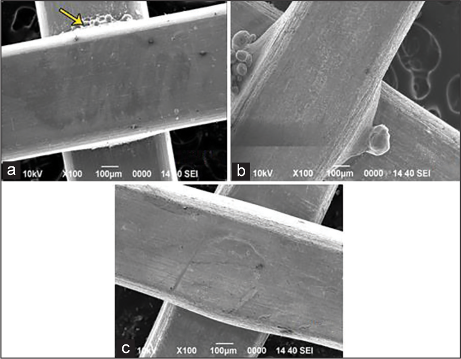
- Scanning electron micrograph showing surface characteristics of the weld samples at ×100. (a) Stainless steel (b) titanium molybdenum alloy (c) tiny (arrow-weld flash)
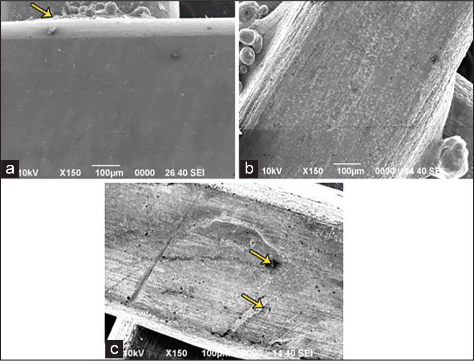
- Scanning electron micrograph showing surface characteristics of the weld samples at ×150. (a) Stainless steel (b) titanium molybdenum alloy (c) titanium-niobium (arrows-voids and microcracks)
Metallographic evaluation
Representative micrographs of the polished and etched weld joints for the three alloys revealed the following details.
Stainless steel
Good fusion with well-defined nugget formation was observed [Figures 3a and 4a]. Cracks were seen at the end of the nugget extending partly into it. There was a change in the linear/fibrous arrangement of grains in the parent metal to a columnar pattern in the weld area indicating a change of the alloy from a wrought structure to a cast structure. Microstructure of the heat-affected zone shows almost equiaxed grains of austenite with some plastic deformation. Microstructure of the parent metal reveals elongated and partially transformed grains of austenite.
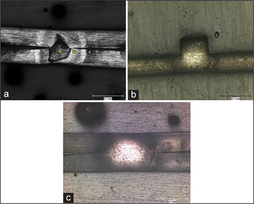
- Optical micrograph showing microstructural changes in the weld samples at ×50. (a) Stainless steel (b) titanium molybdenum alloy (c) titanium-niobium
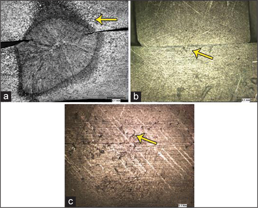
- Optical micrograph showing microstructural changes in the weld samples at ×200. (a) Stainless steel (b) titanium molybdenum alloy (c) titanium-niobium
Titanium molybdenum alloy
Fusion was seen along a line at the region of contact and there was no well-defined nugget formation [Figures 3b and 4b]. Only a “nugget like” zone was seen, which etched bright without any structural details. The “nugget like” region shows fine equiaxed grains of alpha solid solution. Repeated etching only resulted in opening of the fusion line.
Titanium-niobium alloy
A comparable picture to that of TMA archwire was seen with only a “nugget like” zone that etched bright without any structural details [Figures 3c and 4c]. In addition, fine cracks were seen radiating toward the fusion line. Furthermore voids and porosities were observed in the weld zone.
DISCUSSION
The present research was aimed at evaluating the weld properties of Ti-Nb orthodontic archwire alloys and to compare it with SS wires and Titanium molybdenum based beta titanium alloy archwires.
Electrical resistance spot welding continues to be the most commonly used method of joining attachments clinically due to its low cost, simplicity and satisfactory joints. Testing the weld joint strength allows one to evaluate the ability of the joint to withstand the applied orthodontic load without fracture in a clinical situation. Static tensile-shear test is the most preferred method of evaluating the weld joint strength because of its simplicity. The force to cause joint failure with the unit of “Newton” was employed in this study, rather than mean joint strength with the unit of “MPa” or tensile strength with the unit of “N/mm2” obtained from the contact area. Excluding measurements of change in area avoids errors arising from stress concentration and also the “set down” caused by welding. Moreover, the use of force that causes failure of the joint is considered to have greater practical value for comparing welded joints under clinical conditions. This approach was also utilized in the study conducted by Iijima et al.[8] and Donovan et al.[6]
This study indicated that the weld joint strength of TMA wire was significantly higher than that of the Ti-Nb and SS wires, which makes it more desirable for welding of attachments. The difference between Ti-Nb and SS wires was not significant. Both molybdenum and niobium are refractory metals. Care should be exercised to prevent surface contamination with copper welding chills, aluminum, etc., as these form low melting point eutectics, which can severely embrittle the finished joint. Furthermore, the refractory metals incur internal contamination when exposed to the air at elevated temperatures. Absorption of oxygen or nitrogen leads to embrittlement of these metals. The presence of a much higher concentration of a refractory metal (45% niobium) in the Ti-Nb alloy compared to the 11% molybdenum in TMA possibly makes the Ti-Nb alloy more susceptible to contamination and embrittlement. Ideally refractory metals should be welded in an atmosphere protected from re-oxidation. Hence, use of methods such as plasma arc or tungsten arc welding might provide better joint strengths for Ti-Nb archwires. However, these methods are impractical in the orthodontic office.
Surface evaluation with SEM allows analysis of external features of the weld joint and the heat tolerance of the alloy. The poor heat tolerance, leading to a reduction in the strength of the weld joint of SS wires was evident from the surface peeling observed. Absence of cracks and peeling and presence of only minor surface irregularities on the TMA specimen indicate good heat tolerance of the alloy. The good heat tolerance of this alloy correlated well with the good joint strength values obtained. Similar results were seen in the study by Krishnan and Kumar.[9] The surface of the Ti-Nb wires did not show an intact surface or a smooth flow of the metal. Continuity of the surface was broken by voids and cracks. The numerous irregularities seen on the surface [Figure 3c] of these wires indicate a poor heat tolerance of this alloy and probably account for some of the reduction in the mean joint strength. The cracks and voids possibly led to a weakening of the joint. The sensitivity of this alloy to oxidation is evident.
During welding, the temperature exceeds various critical temperatures at which phase transformations occur in the metals involved. In an electrical resistance welded specimen, these changes are a result of localized rapid heating by the concentrated thermal energy from the narrow electrode, followed by rapid quenching from the surrounding cold parent metal. Upon microstructural evaluation, the SS specimens showed a characteristic weld nugget formation indicating a change in the structure of the metal from wrought to cast. The top surface of the SS specimens was deformed indicating a poor heat tolerance of the alloy. The wide heat-affected zone showed the area of weakness of the joint where fracture was most likely to occur. This is a possible reason for the low weld joint strength values obtained for SS specimen.
Micrographs of the TMA specimen did not reveal a characteristic nugget formation. Instead a “nugget like” region was observed that etched bright. No microstructural details can be observed within the joint area. The microstructural changes were limited to a small area and there was less change in the structure of the parent metal producing minimal changes in the properties of the alloy. Only a slight deformation of the top surface was noted. Microstructural defects such as inclusions, microcracks, voids and porosities were rare in the TMA specimen. This correlated well with the higher values of weld joint strength obtained for the TMA group. Similar results were observed in the study by Donovan et al.[6] and Nelson et al.[7] for TMA specimen welded at the optimal voltage setting. A characteristic microstructure was observed by those authors for the specimen welded at higher energy conditions than the optimum one, particularly for the highest settings. In our study, all specimens were welded only according to the optimal voltage setting recommendations of Donovan et al. which explains the similar findings under the optical microscope. Welding of specimen at higher settings caused a visible deformation of the wires and therefore was not used in this study.
The Ti-Nb alloy specimens showed microscopic characteristics superficially similar to those observed for the TMA specimen. There was very little deformation of the top surface. Characteristic nugget formation was not seen for this alloy also. A “nugget like” zone was observed without any structural details. On closer examination the fusion line was seen to be not completely continuous and many microcracks radiating toward the fusion line, voids and porosities were seen. These structural defects were possibly responsible for the lower weld joint strength values obtained for this alloy in comparison with the TMA.
CONCLUSION
Based on the results of this study, it is seen that weld joints in TMA wires have superior strength, surface characteristics and microscopic features compared with Ti-Nb and SS archwires. Therefore in situations where weldability is a desirable characteristic, TMA wires are superior to Ti-Nb wires. The frictional properties of Ti-Nb wires and their ability to be welded to other archwire alloys can be a future area of research.
Source of Support:
Nil.
Conflict of Interest:
None declared.
References
- A review of contemporary archwires: Their properties and characteristics. Angle Orthod. 1997;67:197-207.
- [Google Scholar]
- In-vitro evaluation of the material characteristics of stainless steel and beta-titanium orthodontic wires. Am J Orthod Dentofacial Orthop. 2006;130:460-70.
- [Google Scholar]
- Corrosion behaviour of titanium-containing orthodontic archwires in artificial saliva: Effects of fluoride ions and plasma immersion ion implantation treatment. Chin Dent J. 2005;24:134-40.
- [Google Scholar]
- Optimal welding of beta titanium orthodontic wires. Am J Orthod Dentofacial Orthop. 1987;92:213-9.
- [Google Scholar]
- Joining characteristics of beta-titanium wires with electrical resistance welding. J Biomed Mater Res B Appl Biomater. 2008;85:378-84.
- [Google Scholar]
- Mechanical properties and surface characteristics of three archwire alloys. Angle Orthod. 2004;74:825-31.
- [Google Scholar]