Translate this page into:
Intrusion and retraction with an innovative crane spring


*Corresponding author: V. S. Anusree, Department of Orthodontics, Royal Dental College, Palakkad, Kerala, India. anusree.sasi456@gmail.com
-
Received: ,
Accepted: ,
How to cite this article: Biswas PP, Varsha V, Anusree VS, Hariprasad A, Vaisakh R, Viswanath MN. Intrusion and retraction with an innovative crane spring. APOS Trends Orthod. doi: 10.25259/APOS_157_2024
Abstract
Today, one of the most common lines of treatment for gummy smiles is the use of temporary anchorage devices (TADs). One of the major issues with the TADs is the unpredictability of stability during treatment. Additional to the loosening of TAD, gingival tissue overgrowth, especially when placed above the attached gingiva, is a persistent issue. During the process of intrusion and retraction, the point of force attachment in relation to the center of resistance is of prime importance to achieve the correct and required vector of force. This, at most times, is not achievable with TADs due to the interference of the roots of teeth. Thus, an alternative to TADs with the convenience of placing the point of force attachment anywhere in the buccal vestibule is discussed here in. This article describes the design and action of an innovative spring (Crane spring) wherein the point of force attachment can be varied to suit the biomechanics apart from delivering light and continuous forces using looped mechanics. The spring is of a simple design and can be easily constructed. It is highly efficient with intrusion and retraction.
Keywords
Orthodontics
Gummy smile
Biomechanics
Centre of resistance

INTRODUCTION
A gummy smile is more than 2–3 mm of gum visibility during sustained smiling.[1] The etiology of a gummy smile varies from excess vertical maxillary growth, short upper lip, hyperactive levator muscles of the upper lip, the passive eruption of the upper anterior, and gingival hyperplasia.[2] A clinician must fully understand the various factors involved in the etiology, and a thorough examination followed by the right diagnosis is imperative for achieving an esthetic and predictable result in the treatment of a gummy smile.[3] The article by El-Bokle and Abdel Ghany gives an insight into the etiology of a gummy smile.[4] There have been many modalities of treatment for the same.
In an adult, when a gummy smile has a skeletal origin, such as anterior vertical maxillary excess, a surgical-orthodontic treatment is often the best approach.[4-7] Considering the risks, cost, discomfort, and psychological impact of surgery, the orthodontist occasionally opts for alternative treatment methods.[8] The development of mini-screw bone anchors has outstretched the possibilities of orthodontic treatment.[9] One of the major issues with the temporary anchorage devices (TADs) is the consistency of results, and the stability of TADs is not predictable.
The crane spring was designed to position the point of force attachment as desired by the orthodontist by adjusting the height and length of the active arm. It is very efficient in intrusion and retraction with controlled vectors of force. This case report presents the treatment of an adolescent patient whose gummy smile was corrected by intrusion and retraction of the maxillary anteriors using the innovative crane spring.
CASE REPORT
A 15-year-old, post-pubertal female on extraoral examination revealed a convex profile, mild anterior divergence, a steep mandibular plane angle, and a high clinical (frankfort mandibular plane angle) (FMA). The patient had incompetent lips with a 4 mm interlabial gap, an acute nasolabial angle, and an increased lower anterior facial height of 6 mm. The patient’s smile exhibited a gingival exposure of 5 mm. The etiology of the gummy smile was identified as a short upper lip, hypermobility of the upper lip, increased dentoalveolar height, and vertical maxillary excess, as assessed by the method advocated by El-Bokle and Abdel Ghany[4] [Table 1].
| S. No. | Assessment | Measurement | Measured (A) | Norm (B) | |
|---|---|---|---|---|---|
| Pre | Post | ||||
| 1. | Amount of GD | Tooth zenith – lower border of the upper lip | 5 mm | 0 mm | 1–3 mm ideal- 0 mm |
| 2. | Lip length at rest | a) At philtrum | 16 mm | 17 mm | 21 mm-F 23 mm-M |
| b) At commissures | 21 | 22 | |||
| Diff: a-b | 5 mm | 5 mm | 1–3 mm | ||
| 3. | Upper lip mobility | Upper lip during full smile (s) | 11 mm | 11 mm | |
| Mobility (M)=a-s | 5 mm | 6 mm | |||
| Percent mobility (M%)=M/a×100 | 30% | 35.3% | 27% | ||
| HM: M%-27×a/100 | 0.48 mm | 1.4 mm | 0 mm | ||
| 4. | a) Clinical crown length U1 | Width/length | 8/9×100=88% | 8/9×100=88% | 80% |
| b) Gingival excess | Sulcular depth probing | 1 mm | 2 mm | 1 mm | |
| 5. | a) vertical position of U1 | U1-functional esthetic occlusal plane | 8 mm | 4 mm | 2–4 mm |
| b) angulation U1 | SN-U1 | 114° | 110° | 106±9° | |
| 6. | VME | Rickets maxillary height angle (N-ptm-A) | 54° | 54° | 56±3° |
| 7. | Anterior dental height (COGS) | U1-NF | 30 mm | 27 mm | 30.5°±2.1 mm |
| 8. | N–ANS | 50 mm | 51 mm | 54.7±3.2 mm | |
GD: Gingival display, VME: Vertical maxillary excess, COGS: Cephalometrics for orthognathic surgery
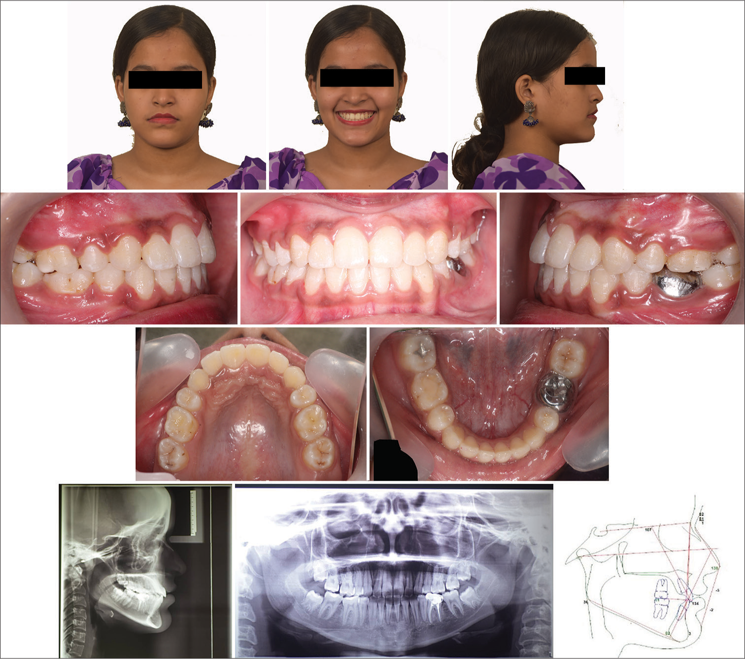
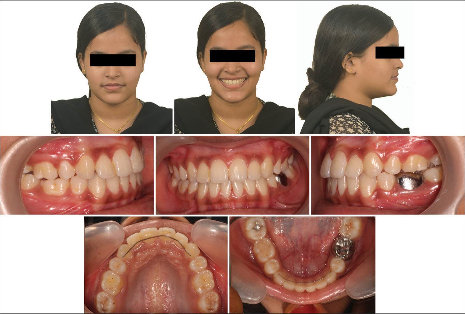
Intraoral examination revealed an Angle’s Class I molar, canine, and incisor relation with 3 mm overjet, 3 mm overbite, and mild spacing in the upper arch. The cephalometrics demonstrated an orthognathic maxilla and mandible on a Class I skeletal base with a vertical growth pattern. The lower anterior facial height was increased by 7 mm with mild proclination of upper and lower incisors. The soft-tissue analysis revealed normal upper lips and protrusive lower lips [Figure 1].
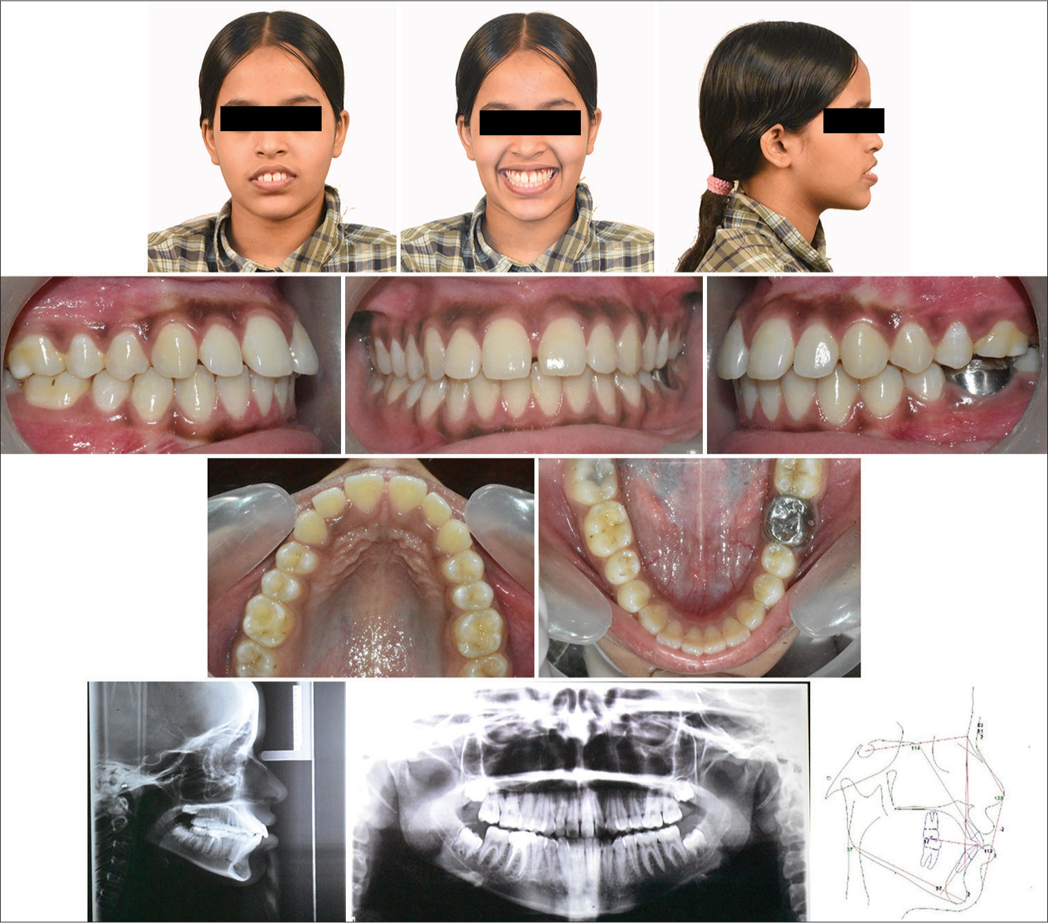
- Pre-treatment.
The primary treatment objective was to correct the gummy smile by simultaneously intrusion and retraction of the anterior bodily.
THE DESIGN OF THE CRANE SPRING
This spring has a specific design [Figure 2] with three arms and two helices. It consists of the lower, middle, and upper arms. The lower arm is inserted into the auxiliary tube from the posterior. This arm ends up posteriorly with a helix (2.5 mm diameter), which, in turn, continues upward to form the middle arm. Subsequently, the middle arm ends up with the second helix (2.5 mm diameter), which, in turn, leads anteriorly to form the upper arm or the free arm. The end of the free arm consists of a hook for the attachment of elastics. The length and height of the free arm can be adjusted as per the biomechanical requirement.
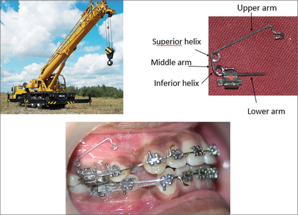
- The design of the crane spring.
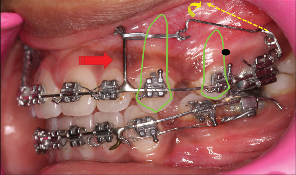
Activation for intrusion is achieved by opening the superior helix such that the end of the free armrests in the sulcus [Figure 3]. In this case report, the vector of force was intended to pass through the center of resistance of the maxillary dentition and this was achieved by placing the free end of the upper arm mesial to the second premolar root apex. The retraction force is obtained by an elastic chain stretched from the free end to the posted archwire.
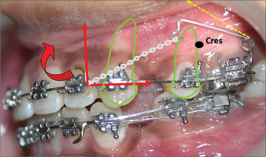
- Activation of crane spring. Cres- Centre of resistance; red curved arrow- moment of anterior segment, red straight arrows-vectors of force, green matter- tooth outline depicting root position, yellow dashed arrow - activated position of the free arm
TREATMENT PROGRESS
After the extraction of all first bicuspids, the patient was strapped up with the Duploslot bracket system (Koden Inc., 244 Fifth Avenue, New York, NY 10001, https://kodenindia.com, [Figure 4]), which consists of 2 slots, a cervical slot of 0.018 × 0.025-inch dimension and an incisal slot of 0.022 × 0.025-inch dimension. The bracket prescription is given in [Figure 5]. After initial leveling and aligning, before retraction, a 0.019 × 0.025 inch posted stainless steel archwire was placed in the upper and lower arches. At this juncture, the superior helix of the crane spring was opened up such that the free end was displaced high up into the sulcus to achieve the intrusive force. The Crane spring was then engaged to the upper arch bilaterally. The free end of the crane spring was positioned at the center of resistance of the maxillary dentition, and an elastic chain was stretched from the free end to the post of the archwire, which was positioned distal to the lateral incisors to achieve a force value of 250 g/side.
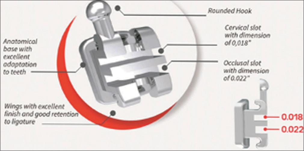
- Duploslot bracket.
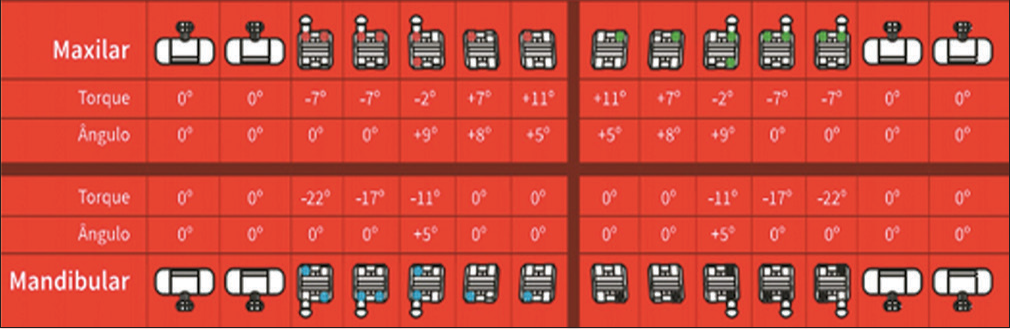
- Duploslot bracket prescription.
With the posterior and superior vector of force passing through the center of resistance (zero moment), it was intended to achieve intrusion and retraction without altering the occlusal plane [Figure 3]. Simultaneous retraction was continued in the lower arch with regular sliding mechanics on a 0.019 × 0.025 posted SS archwire.
The capability of the crane spring was such that the active intrusion caused an open bite to occur [Figure 6]. At this point, it was decided to decrease the intrusive forces and retract the maxillary anterior bodily. Hence, the length of the post placed distal to the lateral incisor was increased such that the force vector would be placed above the center of resistance of the anterior teeth, and retraction was continued [Figure 7].
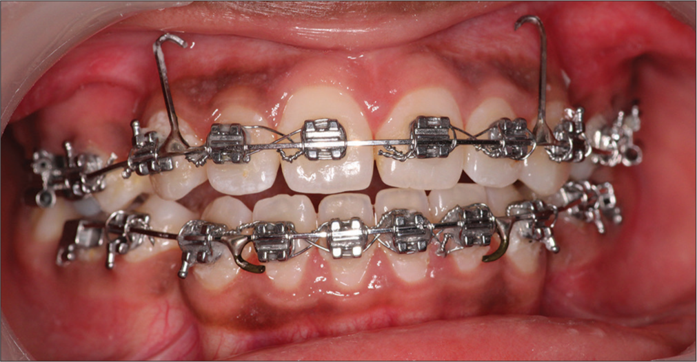
- Open bite after limited intrusion and retraction.
- Bodily retraction with force vector passing through cres of maxillary dentition. Cres- Centre of resistance, red thick arrow - force vector, red thin arrow- occlusal plane, green matter- tooth outline depicting root position, yellow dashed arrow- activated position of free arm, yellow curved arrow- direction of movement of free arm.
During the progress of retraction, clinically, it appeared that the upper anterior was experiencing a torque loss. Thus, it was decided to break the anterior retraction and bring about mesialization of the posteriors. For this purpose, a 0.018 × 0.022-inch sectional SS wire was placed in the cervical slot (0.018 slots), and this sectional wire was tied to the continuous 0.019 × 0.025 inch posted archwire, which was secured in the incisal slot (0.022 slots). The sectional wire was tied to the base archwire between the canines and lateral incisors. At this juncture, the force vector was passed from the tall anterior post to the molar hook such that it would pass above the center of resistance of the anteriors to attain an anticlockwise moment of the incisors [Figure 8].
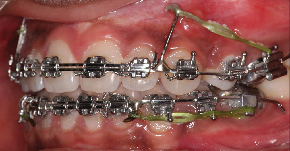
- Change in force vector with anticlockwise moment of anteriors. Sectional 0.018 × 0.022inch SS wire placed in 0.018 cervical slot. Continuous 0.019 × 0.025 inch SS long posted archwire placed in 0.022 incisal slot.
At the end of retraction, a lateral cephalogram was taken to assess the torque of the maxillary anterior, and it demonstrated a torque loss of 3°. Subsequently, a 0.019 × 0.025 pretorqued NiTi (G and H Wire company, USA, https://www.ghorthodontics.com) of 20° torque for the anteriors [Figure 9] was placed for 3 months and the torque values were corrected [Figure 10] and the appliance was debanded.
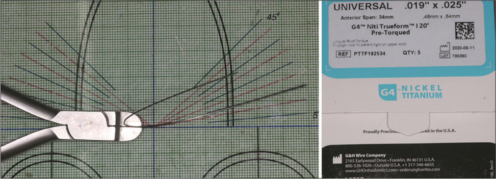
- Pre-torqued NiTi (20° anterior torque).
![Torque correction of 3°. Redline- long axis of the upper incisor green line - facial axis [Ptm(ptrygomaxillary fissure) to Gnathion].](/content/9/2024/0/1/img/APOS-157-2024-g010.png)
- Torque correction of 3°. Redline- long axis of the upper incisor green line - facial axis [Ptm(ptrygomaxillary fissure) to Gnathion].
TREATMENT RESULTS
In the post-treatment, the patient ended up in an esthetically pleasing profile with competent lips. Most importantly, the gingival exposure of 5 mm during the smile was completely corrected [Figure 11]. A comparative evaluation of pre-treatment and post-treatment gummy smiles is given in [Table 1]. Intraorally, the spacings were closed and the anteriors were positioned with ideal axial inclinations [Figure 12]. The cephalometric Composite analysis is given in Table 2.
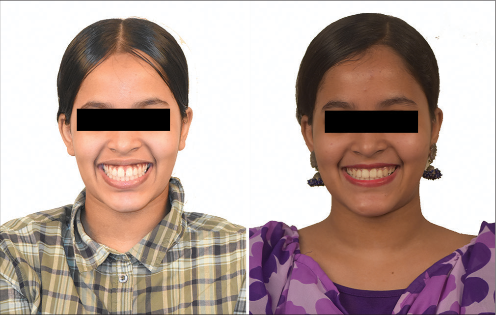
- Gummy smile correction.
- Post-treatment.
| SL No | Measurement | Mean | Pre-treatment | Post-treatment |
|---|---|---|---|---|
| 1 | N perp to A | 0±2 mm | −1.6 mm | −2 mm |
| 2 | N prep to Pog | 0–−4 mm | −4.8 mm | −3 mm |
| 3 | Wits | 0 mm | −4 mm | −2 mm |
| 4 | GO-GN to SN | 32° | 37.5° | 36.6° |
| 5 | IMPA | 90°±3° | 97.2° | 82° |
| 6 | LAFH | 63 mm | 70 mm | 68.6 mm |
| 7 | Jarabak ratio | 62–65 | 60.9% | 61.4% |
| 8 | SNA | 82°±2° | 82.5° | 81° |
| 9 | SNB | 80°±2° | 81° | 82° |
| 10 | ANB | 2° | 1.5° | −1° |
| 11 | UI to NA (Linear) | 4 mm | 10.3 mm | 5.8 mm |
| 12 | UI to NA (Angular) | 22° | 31.2° | 31° |
| 13 | LI to NB (Linear) | 4 mm | 8.6 mm | 2.8 mm |
| 14 | LI to NB (Angular) | 25° | 35.5° | 18.8° |
| 15 | UI to PP | 70°±5° | 60° | 61° |
| 16 | E line to upper lip | 2–3 mm | 2 mm behind | 4 mm behind |
| 17 | E line to the lower lip | 1–2 mm | 3 mm ahead | 2 mm behind |
pog: Pogonion, GO-GN: Gonion- Gnathion, SN: Sella-Nasion, IMPA: Incisor Mandibular plane angle, LAFH: Lower anterior facial height, SNA: Sella-nasion-point A, SNB: Sella-nasion-point B, ANB: Point A-nasion-point B, U1 to NA: Upper inciosr to Nasion- point A, L1 to NB: Lower incisor to nasion-point B, U1 to PP: Upper incisor to palatal plane
Rickett’s 4-stage superimposition revealed that the upper incisors intruded by 3 mm, while the upper molar exhibited an extrusion of 1 mm [Figure 13]. One-year post-treatment photographs showed that the results were stable [Figure 14].
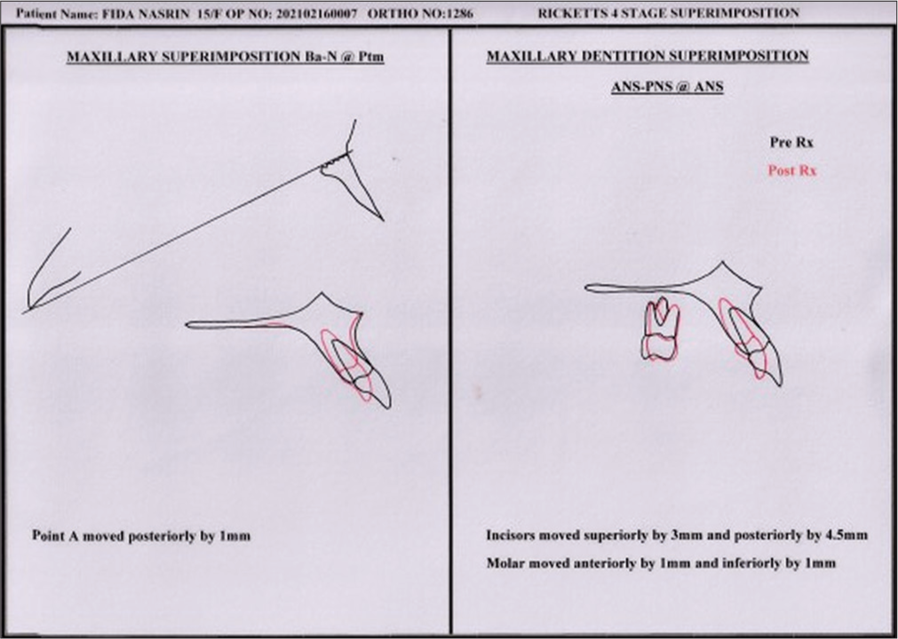
- Superimposition. ANS-PNS: Anterior nasal spine -posterior nasal spine, Rx: Treatment
- One-year post-treatment.
DISCUSSION
In the present case report, the primary objective of treatment was the correction of the gummy smile with true intrusion and retraction of the upper anterior teeth using the crane spring. In general, the point of force application decides the vector of intrusion and retraction. The more anterior the point of force application, the more intrusive the forces are. Thus, it is very important to locate accurately and position the point of force attachment. With this spring, this is attained by altering the length of the active arm. Hence, the crane spring has the flexibility of positioning the tip of the free arm both in the vertical and horizontal dimensions (anteroposterior) so as to alter the point of force attachment in relation to the center of resistance of the dentition. Presumably, this is easily done with TADs, but in reality, the roots of anterior teeth do not make it permissible always. Furthermore, the consistency of stability of TADs is also questionable. Moreover, the cost of two TADs is an added demerit.
Even though a torque loss of 3° was observed in this case, efforts were made to maintain torque during retraction using the double-slot brackets. The retraction force was applied above the center of resistance with an anterior long post positioned distal to the lateral incisors, facilitating bodily retraction of the anteriors. Later, a sectional wire (0.018 × 0.025 inch) was placed in the gingival slot which functioned as a brake. This setup simulated four-spur torquing auxiliary similar to the Begg technique, helping to control and correct the torque during the retraction phase.
When compared to Burstone’s three-piece intrusion arch, the crane spring allows for three-dimensional adjustments (vertical, transverse, and anteroposterior), providing greater versatility in achieving the desired tooth movements. The crane spring’s point of force application is closer to the center of resistance of the maxillary dentition, providing more controlled intrusion and retraction. As retraction progresses, the force vector can be adjusted by changing the length of the free arm. The crane spring’s double helices also deliver lighter, continuous forces, which can be more comfortable for the patient and reduce the risk of root resorption.
CONCLUSION
The Crane Spring is an effective device for correcting gummy smiles with true intrusion and retraction of the anterior. It allows the placement of the point of force attachment anywhere as per the biomechanics requirement. Its high intrusion efficiency caused a remarkable open bite. It is simple to fabricate and incurs no extra cost. The helical design delivers light and continuous forces.
Ethical approval
The Institutional Review Board approval is not required.
Declaration of patient consent
The authors certify that they have obtained all appropriate patient consent.
Conflicts of interest
There are no conflicts of interest.
Use of artificial intelligence (AI)-assisted technology for manuscript preparation
The authors confirm that there was no use of artificial intelligence (AI)-assisted technology for assisting in the writing or editing of the manuscript and no images were manipulated using AI.
Financial support and sponsorship
Nil.
References
- Excessive gingival display--etiology, diagnosis, and treatment modalities. Quintessence Int. 2009;40:809-18.
- [Google Scholar]
- A systematic diagnostic scheme for excessive gingival display “gummy smile”. AJO DO Clin Compan. 2022;2:335-43.
- [CrossRef] [Google Scholar]
- Bimaxillary orthognathic surgery in a patient with long face: A case report. Int J Adult Orthod Orthog Surg. 1999;14:304-9.
- [Google Scholar]
- Surgical-orthodontic correction of long-face syndrome. J Clin Orthod. 2006;40:323-32.
- [Google Scholar]
- Contemporary treatment of dentofacial deformity Vol 11. St. Louis: Mosby; 2003. p. :500-506.
- [Google Scholar]
- Treatment of skeletal-origin gummy smiles with miniscrew anchorage. J Clin Orthod. 2008;42:285-96.
- [Google Scholar]