Translate this page into:
A century of the edgewise appliance
Address for correspondence: Dr. James L. Vaden, Private Practice, Cookeville, TN, USA. E-mail: jlvaden@frontiernet.net
This article was originally published by Wolters Kluwer and was migrated to Scientific Scholar after the change of Publisher.
Abstract
The edgewise appliance, born in the mind of Dr. Edward Angle and first introduced on June 2, 1925, has withstood the test of almost a century of time and usage. The 022 standard appliance that Angle described in a series of four articles in Dental Cosmos is being used by many orthodontic clinicians in fundamentally the same form as it was presented in 1928 and 1929 in Dental Cosmos. Yes, it has been modified in innumerable ways. However, to use one of the modifications, the clinician must understand and respect the fundamentals of its use. This treatise describes the appliance’s evolution from Angle to its use today. The force system of today is simpler and more refined than what Angle envisioned but the appliance is “intact.” It is as modern as tomorrow and will continue to be used as long as the specialty exists. It was Angle’s greatest contribution.
Keywords
Edgewise
ribbonarch
pin and tube

The edgewise appliance has been used in orthodontics for almost a century. It had its beginnings in the mind of Edward Angle, the “father of orthodontics” [Figure 1]. During the early 1900s, angle constantly tried to improve the appliances that he used — and that he sold through dental supply houses. Angle’s ribbon arch appliance and the older pin and tube appliance were proving difficult to use. Other “appliances” were marketed, but most of them were a hodgepodge of expansion screws and finger springs. In the mid-1920’s, Edward Angle felt the necessity to “invent” something that was better than anything available. On June 2, 1925 at the Fourth Annual Meeting of the Edward Angle Society of Orthodontists, he gave the fledging orthodontic specialty a glimpse of the edgewise appliance. He described his new appliance again in a 1926 lecture in Pasadena, California and once more during another lecture on June 28, 1928 at the Seventh Annual Meeting of the Angle Society. Because his new appliance had not been widely accepted, angle decided that he must describe the appliance in detail in printed form. He did so in a popularly circulated journal, the Dental Cosmos. Because it is fascinating to read Angle’s description of his struggles with his edgewise appliance, the following is a direct excerpt from the Dental Cosmos article of December 1928.[1] The excerpt gives one a good understanding of the introduction of the edgewise appliance and the mental anguish that it caused for its inventor, Edward Angle. [Angle used Figure 2 in his article to illustrate the appliance. It is Figure 2 in this article as well].

- E.H. Angle

- Edgewise appliance
Few of you will be able to realize what a struggle it has cost me to introduce a seeming rival to my own precious offspring, the ribbon arch mechanism. However, we are not our own masters. Some invisible hand is always pushing us on to do, or try to do, what it seems we must, not always what we would. So far, in reality, we shall later see that the new is not truly a rival, but that by their union the two mechanisms may be made harmonious and even cooperative, in many instances to the benefit of both, especially to the ribbon arch mechanism, and that thus our mechanical resources for treatment are widened and strengthened.
The principles of application and operation of the mechanism, which I shall now describe, are, in the main, along the line of those with which you are already familiar, those of the time-honored labial arch mechanism here made use of in devices of further refinement. In fact, as we shall see, in this mechanism are combined most of the best points of all my former types of expansion arch mechanism, that is, the arches E and B, the arch with pin and tube attachments, and all forms of the ribbon arch mechanism, and, besides, it has many other distinct advantages peculiar to itself. Figure 2 illustrates all of the various parts of the new mechanism.
A shows a band which is 1/8 inch wide, 1¾ inches long, and 0.004 inch thick, with a bracket brazed to the center of its labial surface. The bracket is made from a solid block of metal and has a slot cut horizontally across it midway of its length. The outer ends of the bracket are beveled from the slot to the edges of the band. You will note how delicacy and strength are combined in its proportions. It is designed, especially for use on anterior teeth, although it may be used in any part of the mouth. This will be known as open-face bracket No. 1.
B shows another band of the same dimensions as that shown at a, but bearing a somewhat different type of horizontally slotted bracket, the portions of the bracket above and below the slot, instead of being beveled, forming overhanging flanges or wings. It is designed for use on buccal teeth and will be known as open-face bracket No. 2.
The slots in both brackets are for the reception of metal arches, the active or power members of the mechanism.
C and D show the two types of bracket bands, seated within the brackets of which are segments of two types of elastic arch material of which the arches are to be made, the form of arch used to be determined according to the requirements of particular cases. The one shown at C is rectangular in form and made from a bar of metal of the same material as that of which the tiny ribbon arches, used on deciduous and mixed dentitions, are made. It is carefully drawn to the dimensions of exactly 0.022 inch in thickness and 0.028 inch in width, and it most accurately fits the slots in both brackets. That at D is round and but 0.022 inch in diameter, of the same material as that you have been using for spurs, retention and, occasionally, for arches in the tiny ribbon arch mechanism.
The two types of arch shown at A and B are interchangeable in the two types of brackets.
It will be noted that the rectangular arch is applied edgewise to the brackets instead of sidewise or flatwise, as in its use in the ribbon arch mechanism. For this reason, it will hereinafter be designated the edgewise arch, to distinguish it from the ribbon arch that also is rectangular in form. Used in this novel manner, the arch is more delicate and graceful in appearance, besides having greater power under certain conditions and far greater elasticity or range of operating force under others, as in widening dental arches, effecting some forms of root movement, tipping teeth into their correct upright axial relations, etc.
Dr. Edward Angle described the edgewise bracket and the use of the appliance in a series of three more articles in the Dental Cosmos.[2-4] He died on August 11, 1930 at the age of 75. He did not have time to teach the appliance’s manipulation or to make any improvements. These duties had to be left to others — his students and colleagues. In his lecture on June 28, 1928 at the Seventh Annual Meeting of the Angle Society at New London, Connecticut, Angle touted the fact that the edgewise appliance, as he saw it, was much simpler and much easier to use than the ribbon arch. He talked about its efficiency and told his audience that actual clinic patients would be available for examination by all attendees later during the day of his lecture so that everyone could critically inspect the results edgewise obtained with the appliance.[4] When the appliance was introduced, several of Angle’s earlier students, one in particular, Dr. Allen G. Brodie, used the edgewise appliance exclusively. These practitioners echoed Angle’s claims that the newly introduced appliance was much more “user-friendly” than anything else available.
Charles Tweed graduated from an improvised Angle course that was given to him and four other students by George Hahn and some Angle school graduates. It was an improvised course because Angle accepted the five students and subsequently closed his school. The students showed up for Angle’s school, but Angle had gone to Hawaii. George Hahn organized the 1928 session — the last session of the Angle school. Angle returned and interacted with Tweed and his classmates, gave some lectures, etc. Tweed’s graduation date was 1928. Charles Tweed was 33 years of age while he was studying in the Angle school. Immediately after his schooling was completed [Figure 3], Tweed helped Angle with the Dental Cosmos articles that were being readied for publication. Angle convinced young Tweed that he (Tweed) could never master the edgewise appliance unless he limited his practice solely to its use. Charles Tweed returned to his home of Phoenix, Arizona and established a pure edgewise specialty practice. Tweed worked closely with Angle for the last 2 years of Angle’s life. It is documented by letters between the two men housed in the Tweed Memorial Library that Tweed took many of his active treatment patients by train to Pasadena to have Angle examine them. Angle would offer Tweed a plan for each patient’s next course of treatment. Tweed would return to Phoenix with his patients and complete the treatment advised by Edward Angle. The two men became very close friends and were in constant contact during the last 2 years of Angle’s life.
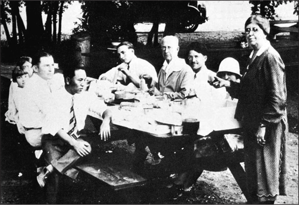
- Tweed at a picnic with Angle
Tweed used Angle’s nonextraction philosophy until he became disheartened with the protrusive faces that he was creating. By 1932, he had decided that he must study his failures and his successes. During the 4 years period from 1932 until 1936, Tweed made many important observations. One of these was that the patient who had the best balance and harmony of facial proportions had mandibular incisors that were not protruded off the basal bone. He concluded that one must, in many instances, extract teeth to upright mandibular incisors to have a balanced face. In 1936, Tweed delivered to the membership of the Angle Society an “extraction” paper. He was severely criticized.
He subsequently published this paper on the extraction of teeth for orthodontic malocclusion correction.[5,6] The paper caused quite a stir throughout the orthodontic world. Tweed continued his work, and by 1941 had become known for his clinical expertise and his skill at the manipulation of the edgewise appliance. The Tweed Study Course was born as a result. The purpose of the Course was to teach Tweed’s treatment planning protocols as well as the use and manipulation of the edgewise appliance.
The 1941 Tweed Study Course was held in Joe Doebrick’s machine shop. World War II intervened. The Course was started again in 1946 in a “new” facility, one that is still in use. Tweed continued to organize his Tweed Study Course and taught literally thousands of orthodontists, both those who were university trained as well as preceptees, how to use the edgewise appliance. He lectured and published[7-14] extensively during the 1950’s and 1960’s. His 1966 two volume text[15] is copiously illustrated with wire manipulation bends and wonderful drawings of hand positions with very detailed explanations of how each finger should be moved to make a particular bend in the archwire. What Tweed did that Angle did not have time to do was devise a force system that would allow the appliance to work as it should work.
The malocclusion of the patient determined, in many instances, how Tweed used the appliance. Whether or not the patient had to be treated with extractions or treated without extractions had a great bearing on the archwires and on the extraoral forces that were employed. To look at the pictures of the various typodont malocclusion corrections that were photographed and illustrated in Tweed’s textbook is a very interesting and eye-opening experience.
In Tweed’s day, each patient’s malocclusion correction would require between 10 and 12 sets of archwires [Figures 4 and 5]. Because of the many elastic and headgear forces that were applied to the archwires, the big unknown was patient cooperation. On page 176 of volume 1 of his text, Tweed states, “With these reactions thoroughly understood, it becomes obvious that patient cooperation is most important for success in treatment objectives. If the forces are not controlled because the patient does not follow instructions, disaster lies ahead, particularly in nonextraction cases. If second order bends are placed in the maxillary archwire unaccompanied by Class II intermaxillary force, the uncontrolled forces will move the root apices of the teeth in the buccal quadrants from the terminal molars to cuspids in a mesial direction, with no appreciable distal movement of their crowns. In such instances, treatment will produce a mesial displacement of the teeth in the buccal quadrants of both arches and the end result will be a bimaxillary protrusion due to forces improperly utilized.” Tweed went on to talk about the creation of anterior openbites if the patient did not properly wear the forces during en masse anchorage preparation. Tweed essentially used Angle’s edgewise appliance in the following manner. The steps were:
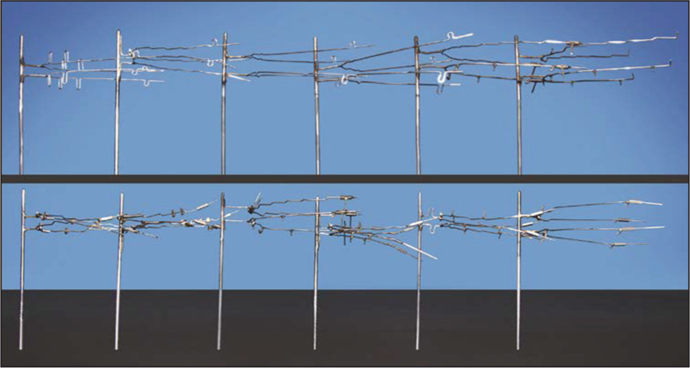
- Twelve sets of archwires
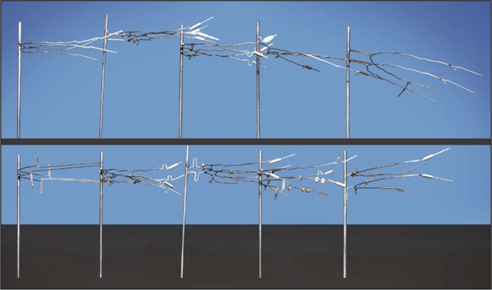
- Ten sets of archwires
Leveling and alignment — A series of round archwires was used. During his later years, Tweed used directionally controlled headgear applied to the canines to begin canine retraction on these round archwires [Figure 6].
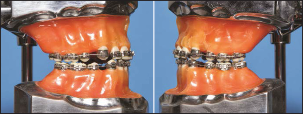 Figure 6
- Round archwires used during leveling
If teeth were extracted, mandibular extraction space closure was accomplished after leveling and alignment. This was done with a 0.020 × 0.025 working archwire that had closing loops incorporated into them [Figure 7].
 Figure 7
- Closing loop archwires
Mandibular anchorage preparation — To prepare mandibular anchorage, Tweed bent a stabilizing archwire for the maxillary arch and a working archwire for the mandibular arch. All mandibular second order bends were placed, at one time, into the archwire [Figure 8]. To control these second order bends, Tweed used Class III elastics, an intermediate headgear to the maxillary arch and vertical up and down elastic force.[8]
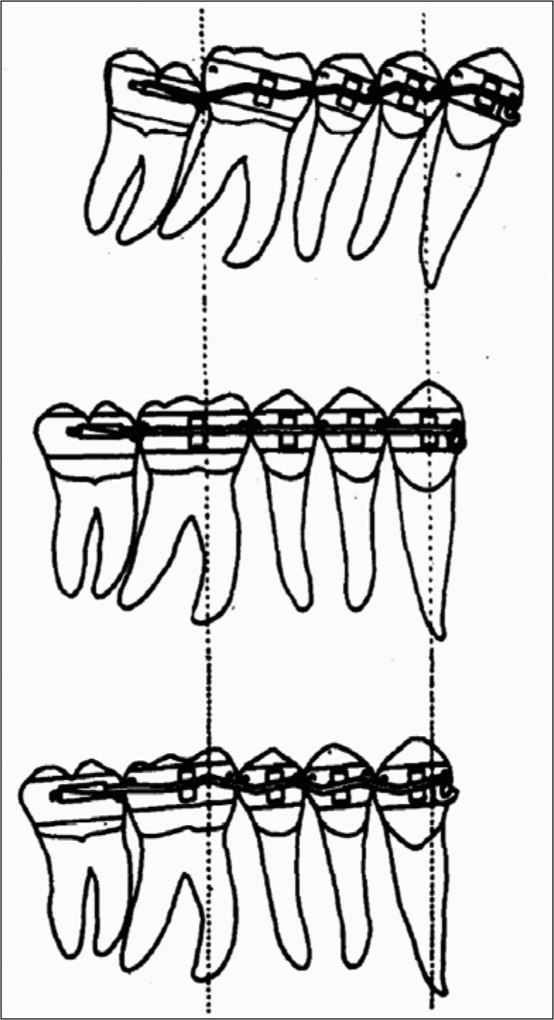 Figure 8
- En masse anchorage preparation
After en masse mandibular anchorage had been prepared, the mandibular arch was stabilized with an 0.0215 × 0.028 archwire that was continuously tied in the posterior segments. This stabilizing archwire was an exact “duplicate” of the previously used working archwire, only larger. The maxillary archwire was changed to a smaller dimension maxillary working wire. Tweed then distalized the maxillary arch if the treatment was nonextraction or retracted the maxillary anterior teeth if the patient had extraction space mesial to the distalized maxillary canines. The patient generally wore Class II elastics, anterior vertical elastics, and again, a headgear.
The final step was to finish the correction of the malocclusion. Tweed used 0.0215 × 0.028 rectangular archwires with soldered spurs and vertical elastics to effect the proper interdigitation of the teeth.
This treatment protocol, devised by Tweed, was very effective. Patient cooperation was the key. A noncooperative patient presented problems. The fabrication of 10 to 12 sets of archwires for each patient was, to say the least, a concern for many who used Tweed’s methods.
In 1970 L. Levern Merrifield [Figure 9] of Ponca City, Oklahoma became the Tweed Study Course Director. He and Tweed had worked closely together and discussed many, many things about the edgewise appliance and its use during their years as co-directors of the Course from 1960 until Tweed’s death in 1970. Levern Merrifield was determined to make the use of the appliance more “efficient” while remaining true to Tweed’s concepts of anchorage preparation with vertical control during protrusion reduction. After years of study and experimentation, Merrifield introduced a totally new concept: Edgewise Sequential Directional Force Technology.[16] This system would “streamline” the use of Angle’s invention — the edgewise appliance. Merrifield’s diagnostic and treatment concepts[17-20] included total space analysis, differential diagnosis, sequential appliance placement, directional force control during treatment, sequential tooth movement and, most important, sequential mandibular anchorage preparation. Sequential appliance placement made it possible to use only edgewise archwires. Round wires were eliminated; the dentition was therefore under more control from the outset. Headgear cooperation was essential for directional force control, but sequential tooth movement, particularly sequential anchorage preparation, made patient cooperation much less intense and more manageable. Gone were the Class III elastics for en masse anchorage preparation and the tax that this elastic force levied on the maxillary arch.

Levern Merrifield
Merrifield’s Tweed-Merrifield Force System revolutionized the use of the edgewise appliance. This force system, along with a differential diagnostic analysis system, has been taught since 1982 to thousands of students who have taken the Tweed Study Course.
Merrifield’s concepts remained true to Tweed’s philosophy; they simply made malocclusion correction more reliable and predictable. Since Merrifield’s original work, Herb Klontz[21-23] and other Tweed Study Course instructors have further refined the use of the edgewise appliance. The edgewise appliance of today is as modern as next week; it is efficient; it gives the clinician a very predictable, high-quality result for each patient. A description of the steps of treatment with illustrations follows.
Steps of treatment
Tweed-Merrifield edgewise directional force treatment can be organized into four distinct steps: Denture preparation, denture correction, denture completion, and denture recovery. During each step of treatment, certain objectives must be attained.
Denture preparation
Denture preparation prepares the malocclusion for correction. Objectives include the following:
Leveling.
Individual tooth movement and rotation correction.
Retraction of maxillary and mandibular canines.
The denture preparation step of treatment takes about 6 months. One mandibular archwire and one maxillary archwire are used to complete this step.
The teeth of the original malocclusion are sequentially banded and bonded [Figure 10]. After the placement of the appliance, an 0.018 × 0.025 inch resilient mandibular archwire and an 0.017 × 0.022 inch resilient maxillary archwire are inserted. The mandibular second molar receives an effective distal tip that will upright its mesial inclination. In the maxillary arch, a 20° tip is placed in the wire distal to the omega loop stop to maintain the distal inclination of the second molar.
- Denture Preparation: Initial arch wires. Initial arch wires consist of a 0.017 × 0.022 inch resilient mandibular arch wire
High pull J-hook headgear is used to retract maxillary and mandibular canines. After the 1st month of treatment, the maxillary first molars are banded, and after the 2nd month of treatment the mandibular first molars are banded. As the canines retract, and the arches are leveled, the lateral incisors are ligated, and power chain force to aid canine retraction can be used [Figure 11].
- Denture Preparation: Canine retraction. The canines are retracted with a J-hook headgear during denture preparation
At the end of the denture preparation stage of treatment the dentition should be level, the canines should be retracted, all rotations should be corrected, and the mandibular second molars should be level [Figure 12].

- Completion of denture preparation
Denture correction
The second step of treatment is called denture correction. During denture correction, the spaces are closed with maxillary and mandibular closing loop archwires. Vertical support to the maxillary arch is achieved with J-hook headgear attached to hooks soldered to the maxillary archwire between the maxillary central and lateral incisors. Vertical support of the mandibular anterior teeth is accomplished with anterior vertical elastics. The mandibular archwire is an 0.019 × 0.025 inch working archwire with 7.0 mm vertical loops distal to the lateral incisor brackets. The 0.020 × 0.025 inch maxillary archwire has 7.5 mm vertical loops distal to the lateral incisor brackets. In both arches, the omega loop stops are immediately distal to the brackets of the first molars [Figure 13]. At the end of space closure [Figure 14], the curve of occlusion in the maxillary arch should have been maintained, and the mandibular arch should be completely level. The dentition is now ready for mandibular anchorage preparation.
- Denture correction: Closing loop application
- Space closure. After space closure the arch is level
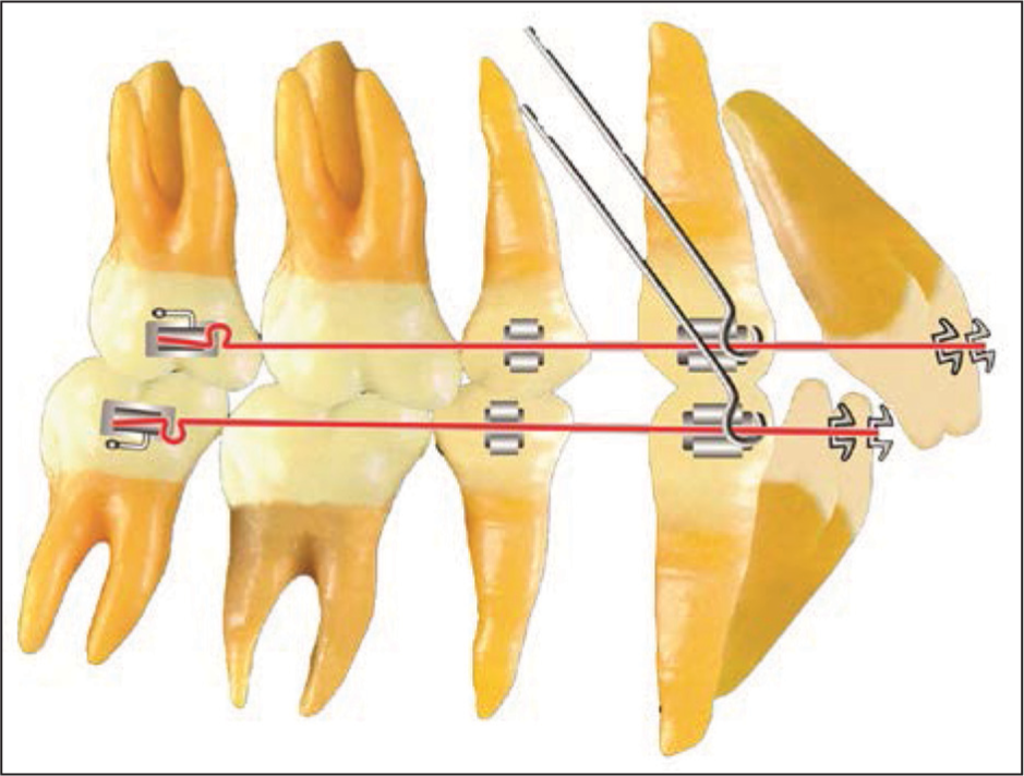
Sequential mandibular anchorage preparation
An 0.019 × 0.025 inch archwire with the omega loop stops bent flush against the second molar tubes is fabricated. First and third order bends are ideal. Gingival spurs for anterior vertical elastics are soldered distal to the lateral incisors.
To tip the mandibular second molars to an anchorage prepared position, a 15° tip is placed distal to the omega loop stop. The second molar is tipped to an anchorage prepared position. It should have a distal inclination of 10 to 15° that can be verified with a readout [Figure 15].[22]
- Mandibular anchorage preparation. The second molar is tipped to its anchorage prepared position
After the second molar has been tipped the first molar is tipped to its anchorage prepared position by placing a 10° distal tip 1 mm mesial to the first molar bracket. When this first molar tip is placed in the archwire, a compensating bend that maintains the 15° second molar inclination must be placed mesial to the omega loop stop [Figure 16].

- Mandibular anchorage preparation. The first molar is tipped to its anchorage prepared position
The archwire is now passive to the second molar and crosses the twin brackets of the first molar at a 10° bias. After 1 month, the archwire is removed and readout should show a 5 to 8° distal inclination of the first molars. The second molars should continue to readout at 15°.
The denture correction step of treatment should now be complete for the Class I malocclusion. The objectives of the denture correction step are:
Complete space closure in both arches,
Sequential anchorage preparation in the mandibular arch,
An enhanced curve of occlusion in the maxillary arch, and
A Class I intercuspation of the canines and premolars.
Class II force system
For patients with an “end-on” Class II dental relationship of the buccal segments at the conclusion of space closure, a new and different force system must be used to complete the denture correction stage of treatment. A careful study of the cusp relationships will determine the force system required. Making a final diagnostic decision for Class II correction is usually based on:
The ANB relationship,
A maxillary posterior space analysis, and
Patient cooperation.
The Class II force system cannot be used unless compliance requirements are strictly followed by the patient. If one attempts to use the Class II force system without cooperation, the maxillary anterior teeth will be pushed forward off the basal bone.
Class II force system
At the end of sequential mandibular anchorage preparation, a mandibular 0.0215 × 0.028 inch stabilizing archwire is fabricated. Ideal first, second, and third order bends are incorporated into the archwire. The omega loop stop must be 0.5 mm short of the molar tubes, and the wire must be passive to all the brackets. Gingival spurs are soldered distal to the mandibular lateral incisors. The wire is seated and ligated, and the terminal molar is cinched tightly to the loop stop.
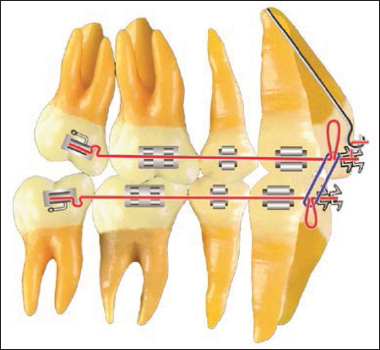
An 0.020 × 0.025 inch maxillary archwire with 7.5 mm closed helical bulbous loops bent flush against the second molar tubes is fabricated. This archwire has ideal first and second order bends. A gingival spur is attached to the archwire immediately distal to the maxillary second premolar bracket. Gingival high pull headgear hooks are soldered distal to the central incisors. Class II “lay on” hooks with a gingival extension for anterior vertical elastics are soldered distal to the lateral incisors. Prior to archwire insertion, the closed helical bulbous loops are opened 1 mm on each side. Class II elastics are worn from the hooks on the mandibular second molar tubes to the Class II hooks on the maxillary archwire. Anterior vertical elastics are worn from the spurs on the mandibular archwire to the gingival extension hooks on the maxillary archwire. The high pull headgear is worn on the maxillary headgear hooks [Figure 17].
- Class II force system
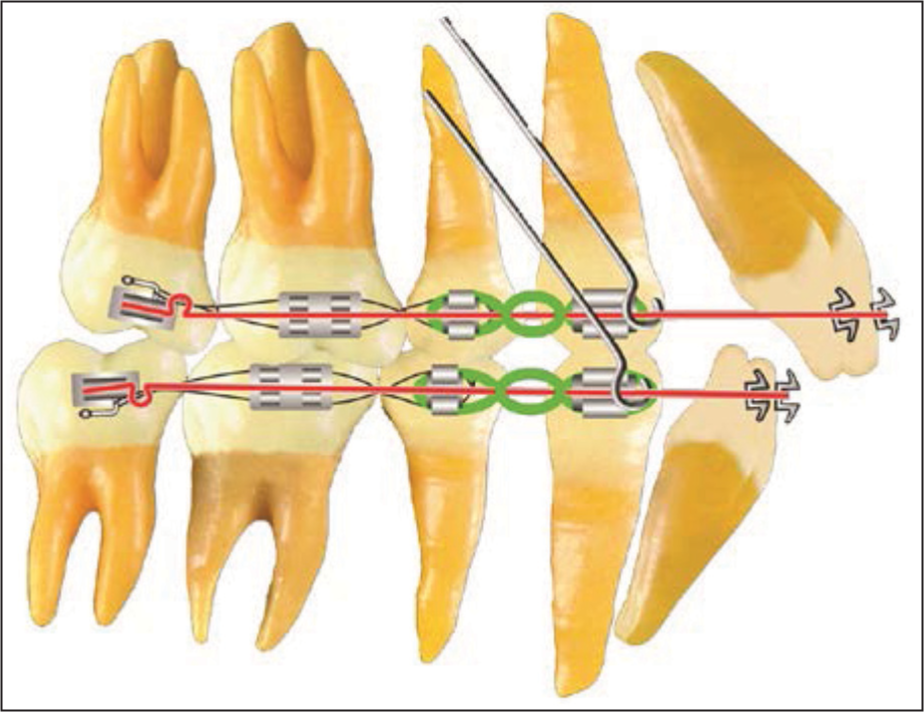
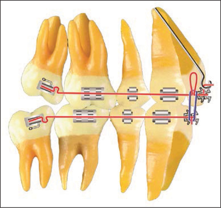
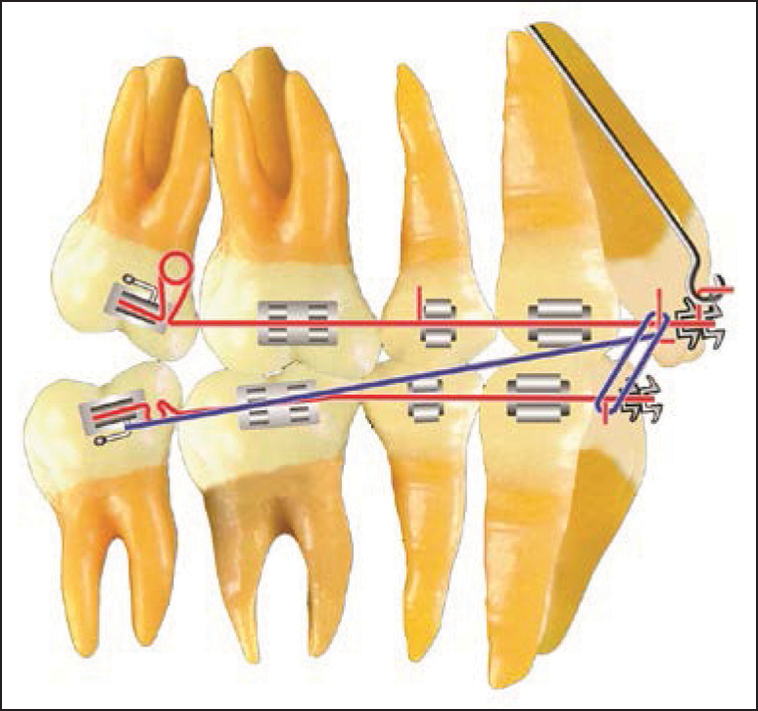
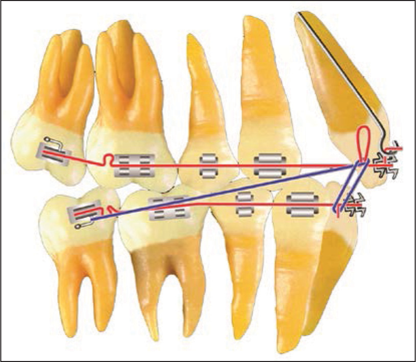
This force system is used to sequentially move the maxillary second molars distally. The activation of the maxillary archwire is repeated until the second molars have a Class I dental relationship [Figure 18]. When the Class I relationship of the second molars has been established, a closed coil spring is “wound” distal to the second premolar spur and compressed between the spur and the first molar bracket when the maxillary archwire is inserted. (The coil spring length should be 1.5 times the space between the second premolar and the first molar brackets). An elastic chain is stretched from the second molar to the distal bracket of the first molar. The spring and the elastic chain create a distal force on the maxillary first molar. In addition, Class II elastic is continuously worn from the mandibular second molar hook to the Class II hook on the maxillary archwire. An anterior vertical elastic is worn 12 h each day [Figure 19]. The high pull headgear is worn 14 h/day on the spurs soldered to the maxillary archwire.

- Class II force system. Denture Correction: The helical bulbous loop pushes the maxillary molar distally

- Class II force system. Denture correction: A coil spring is trapped mesial to the first molar
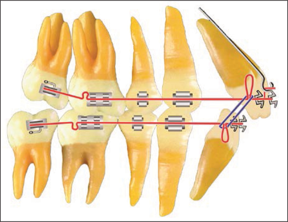
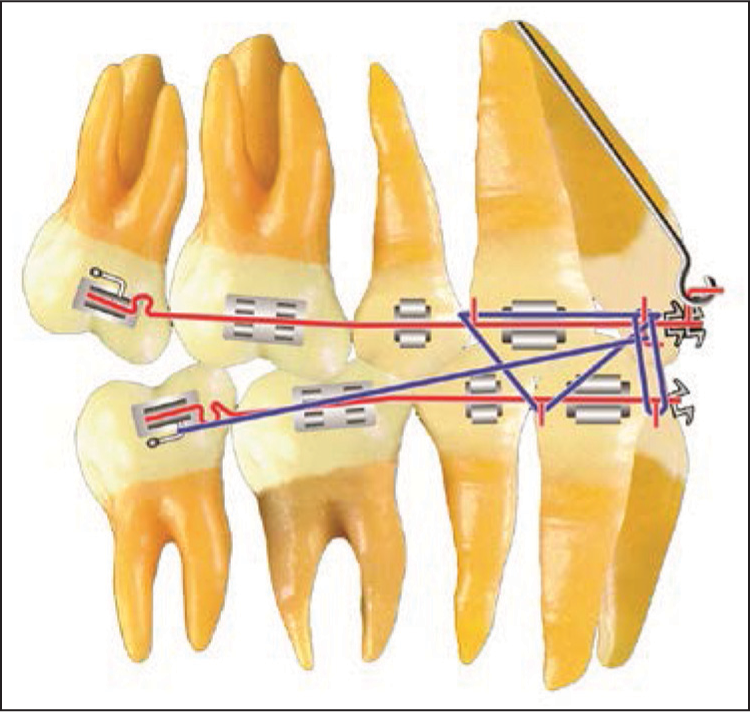
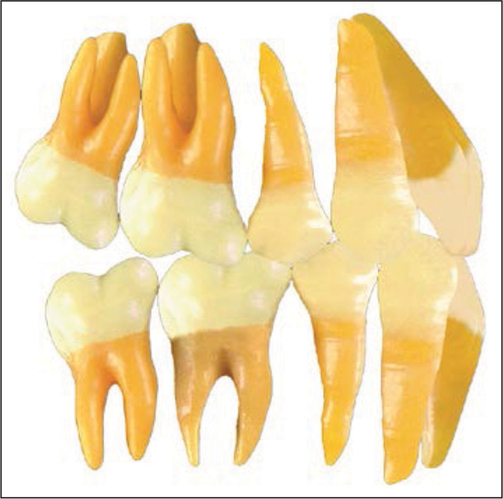
After the first molars have been moved distally into an overcorrected Class I dental relationship, [Figure 20], the spur that was attached distal to the second premolar bracket is removed. The coil spring is moved mesially so that it is compressed between the lay on the hook and the canine bracket. Subsequently, the maxillary second premolars and the maxillary canines are moved distally with elastic chain and headgear force [Figure 21].
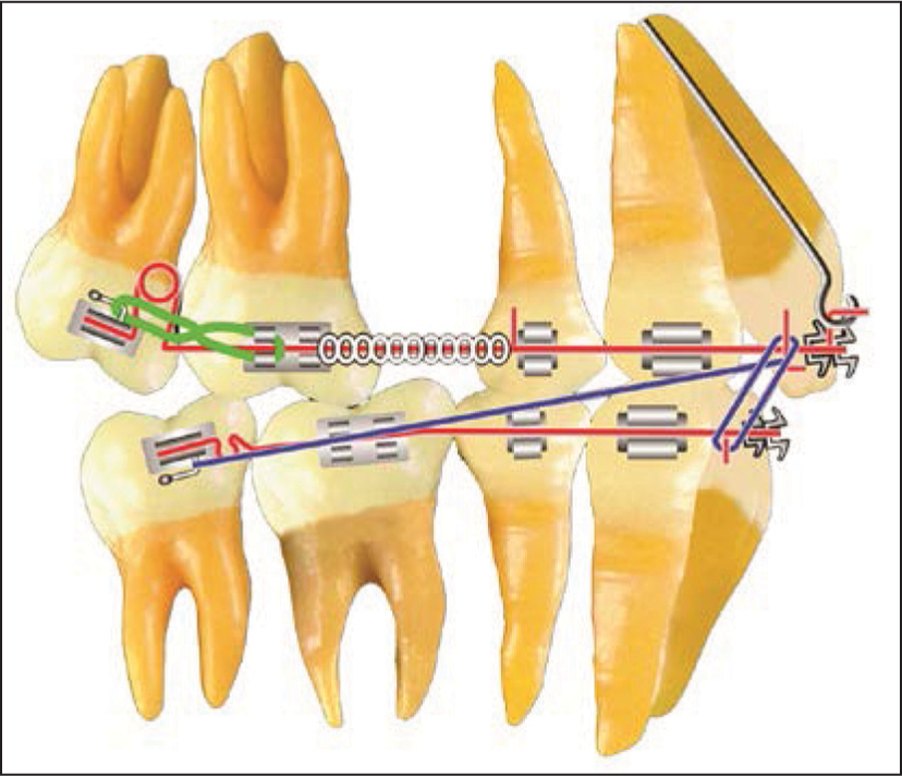
- Class II force system. Denture correction: Maxillary first molar distalization

- Class II force system. Denture correction: Maxillary second premolar and maxillary canine distalization
After overcorrection of Class II dental relationship, an 0.020 × 0.025 inch maxillary archwire with 7.5 mm closing loops distal to the lateral incisors is fabricated. Gingival headgear hooks are soldered distal to the central incisors [Figure 22]. The closing loops are opened 1 mm per visit by cinching the omega loop stops to the molar tube. Class II elastics, anterior vertical elastics and the maxillary high pull headgear are used.
- Class II force system. Denture correction: Maxillary anterior space closure
Denture completion
The third step of treatment is identified as denture completion. Ideal first, second, and third order bends are placed in finishing mandibular and maxillary 0.0215 × 0.028 inch resilient archwires. The mandibular archwire duplicates the previously used mandibular stabilizing archwire. The maxillary archwire has artistic bends and hooks for the high pull headgear, anterior vertical elastics and Class II elastics. Supplemental hooks for vertical elastics are soldered as needed [Figure 23].
- Denture completion. Maxillary and mandibular stabilizing wires, along with the proper elastics and headgear force, are used to complete the orthodontic treatment
The forces used during denture completion are based on a careful study of the arrangement of each tooth in each arch. The orthodontist must also study the relationship of one arch to the other and the relationship of the arches to their environment. Denture completion can be considered as minitreatment of the malocclusion. During this treatment step, the orthodontist uses the forces that are necessary until the original malocclusion is overcorrected.
Denture recovery
An ideal occlusion will be present only after all treatment mechanics are discontinued and uninhibited function and other environmental influences active in the post-treatment period stabilize and finalize the position of the total dentition. When all appliances are removed, and the retainers are placed, a most crucial “recovery” phase occurs. During this recovery period, the forces involved are those of the surrounding environment, primarily the muscles and the periodontium.
The posttreatment occlusion, which is carefully planned, sometimes referred to as Tweed occlusion but properly identified as transitional occlusion [Figure 24], is characterized by disclusion of the second molars. The mesiolingual cusp of the maxillary first molar is seated into the central fossa of the mandibular first molar with the mesial inclined plane of the mesial cusp of the maxillary first molar contacting the distal inclined plane of the mesial cusp of the mandibular first molar. This arrangement allows the muscles of mastication to effect the greatest force on the “primary chewing table” in the midarch area. The slightly intruded distally inclined maxillary and mandibular second molars now can “reerupt” to a healthy functional occlusion without trauma or premature contact [Figure 25].
- Transitional occlusion

- Final occlusion is characterized by the teeth settling into their most efficient, healthy, and stable positions
Angle’s invention, the edgewise appliance, has stood the test of time. Many orthodontists around the world use it today in the form in which it was invented by Angle and refined by Charles Tweed. Orthodontists who use one of the many modifications of the appliance should be very grateful to Angle, to Tweed and to all of those who have laid the foundation for the use of the appliance. Because without a knowledge of the appliance’s foundation, one cannot successfully use any modification.
The standard edgewise appliance is as modern as tomorrow and delivers a very high-quality treatment result to each orthodontic patient. It was Angle’s greatest contribution to the specialty of orthodontics. In today’s world of preadjusted appliances and temporary anchorage devices, a knowledge of and appreciation for the standard edgewise appliance is critical to patient care. The clinician must understand first, third, and second order bends because no appliance is magic — no variation of the standard appliance is magic. The “magic” lies in the proper treatment plan and in one’s ability to use an appliance. Therefore, knowledge of how the standard appliance is currently used is fundamental to the use of any of the innumerable modifications that have been made to Angle’s invention.
ACKNOWLEDGMENTS
We acknowledge the contribution of Sergio Arturo Cardiel Rios for the drawings of Figures 10-25.
Financial support and sponsorship
Nil.
Conflicts of interest
There are no conflicts of interest.
References
- The application of the principles of the edgewise arch in the treatment of class II, division I, part I. Angle Orthod. 1936;6:198-208.
- [Google Scholar]
- The application of the principles of the edgewise arch in the treatment of class II, division I, part II: A discussion of extraction in the treatment of marked double protrusion cases. Angle Orthod. 1936;6:255-7.
- [Google Scholar]
- Indications for the extraction of teeth in orthodontic procedure. Am J Orthod Oral Surg. 1944-1945;42:22-45.
- [Google Scholar]
- The Frankfort-mandibular plane angle in orthodontic diagnosis, classification, treatment planning, and prognosis. Am J Orthod Oral Surg. 1946;32:175-230.
- [Google Scholar]
- Why I extract teeth in the treatment of certain types of malocclusions. Alpha Omegan. 1952;46:93-104.
- [Google Scholar]
- Evolutionary trends in orthodontics, past, present, and future. Am J Orthod. 1953;39:81-108.
- [Google Scholar]
- The Frankfort-mandibular incisor angle (FMIA) in orthodontic diagnosis, treatment planning and prognosis. Angle Orthod. 1954;24:121-69.
- [Google Scholar]
- Was the development of the diagnostic facial triangle as an accurate analysis based on fact or fancy? Am J Orthod. 1962;48:823-40.
- [Google Scholar]
- Treatment planning and therapy in the mixed dentition. Am J Orthod. 1963;49:881-906.
- [Google Scholar]
- Clinical Orthodontics. Vol. I, II. St. Louis: C.V. Mosby; 1966.
- Edgewise sequential directional force technology. J Charles H. Tweed Int Found. 1986;14:22-37.
- [Google Scholar]
- Differential diagnosis with total space analysis. J Charles H Tweed Int Found. 1978;6:10.
- [Google Scholar]
- Differential diagnostic analysis system. Am J Orthod Dentofacial Orthop. 1994;106:641-8.
- [Google Scholar]
- Tweed-Merrifield sequential directional force treatment. Semin Orthod. 1996;2:254-67.
- [Google Scholar]
- The Tweed Merrifield edgewise appliance In: Graber TM, Vanarsdall RL, eds. Orthodontics: Current Principles and Techniques (3rd ed). St. Louis: Mosby; 2000.
- [Google Scholar]