Translate this page into:
Aggravation of Gummy Smile by Straight-Wire Mechanics and its Management with or without Orthognathic Surgery Up to 10-Year Follow-Up
Address for correspondence: Dr. Tsang Tsang Franklin She, Faculty of Dentistry, The University of Hong Kong, Hong Kong, China. E-mail: she@smileclinic.com.hk
This article was originally published by Wolters Kluwer and was migrated to Scientific Scholar after the change of Publisher.
Abstract
Two female patients presented with gummy smile, maxillary dentoalveolar protrusion and total vertical maxillary excess, retroclined incisors, and increased overbite received orthodontic camouflage with straight-wire mechanics by general dentists. The treatments caused severe bowing of upper occlusal plane which aggravated the gummy smile and had led them to seek specialist care. They were successfully managed by orthodontic camouflage and combined surgical-orthodontic treatment, respectively, in conjunction with the application of miniscrews on straight-wire mechanics. Aggravation of gummy smile by straight-wire mechanics, use of visual treatment objective to differentiate between orthodontic camouflage and surgical cases, and LeFort I segmentalization were discussed.
Keywords
Differential moments anchorage
gummy smile
maxillary dentoalveolar protrusion with total vertical excess
orthodontic camouflage with miniscrews anchorage
orthognathic surgery

Introduction
Gummy smile is defined as an excessive display of gingiva when patient smiles.[1] However, defining excessive gingival display is highly subjective. Gingival display of more than 2–3 mm are generally indicated for treatment when patient considers it as an esthetic issue.[2]
There is a list of causes of gummy smile[3] and total vertical maxillary excess[4] is one of them. Maxillary dentoalveolar protrusion, when associates with total vertical maxillary excess, complicates the management of gummy smile as dentolalveolar hyperplasia in both sagittal and vertical dimensions have to be addressed.
Combined surgical orthodontic therapy is the gold standard for treatment as it demonstrated good result with long-term stability.[4-7] However, cost and surgical fear are common reasons which hinder its acceptance.[8]
Orthodontic camouflage with conventional straight-wire mechanics can be a viable option if it is intended to accept gummy smile and protrusion while improving dental alignment.[9,10] On the other hand, if it aims to correct the protrusion by maximum retraction of incisors, there are risks of aggravating gummy smile and opening the bite as the mechanics tends to extrude the teeth. In the circumstances, skeletal anchorage such as orthodontic miniscrew is required for dental intrusion in avoidance of the complication.[10-12]
As orthodontic camouflage with miniscrew anchorage becomes an alternative solution and gains its popularity in the past decade, that is, the question when it comes to when a case should be treated by surgery or its alternative.
This article described the management of two young female adults who presented with gummy smile caused by total vertical maxillary excess in association with maxillary dentoalveolar protrusion. They were treated initially by orthodontic camouflage in conventional straight-wire mechanics with poor results. The problems were subsequently managed successfully by orthodontics camouflage with miniscrew anchorage and surgery, respectively [Figures 1-4]. The choice of treatment was aided by the construction of visual treatment objectives (VTO) which illustrated the difference in their extra-oral features, basal relationship, and occlusion.
- Case 1 orthodontic camouflage: (a) Before (b) After treatment with lips at rest position

- Case 1 orthodontic camouflage: (a) Before (b) After treatment during smile

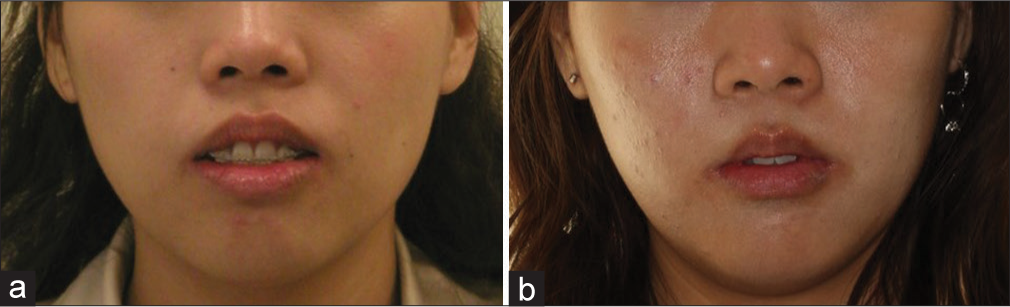
- Case 2 combined surgery orthodontic therapy: (a) Before (b) After treatment with lips at rest position

- Case 2 combined surgery orthodontic therapy: (a) Before (b) After treatment during smile
Case Reports
Case 1
Case history
The patient was a 27-year-old female requested orthodontic treatment from the first author with a chief complaint of worsening of gummy smile and lack of progress of the ongoing orthodontic treatment which was carried out by a general dentist. Extra-oral examination revealed convex profile, protrusive maxilla, retrusive mandible, increased incisal exposure at rest, and gummy smile [Figures 5-7 and Tables 1, 2]. In sagittal dimension, she presented with Class I molar and canine relationship with retroclined upper and lower incisors. Skeletal Class I base with protrusive maxillary dentoalveolar process was recorded. In the vertical dimension, she presented with total vertical maxillary excess, increased overbite due to increased curve of Spee, and overeruption of upper incisors. There was incomplete overbite meaning that upper and lower incisors presented with vertical overlap without interocclusal contact. In the transverse dimension, upper dental midline deviated to the right side. In addition, roots of upper incisors perforated the labial plate of dentoalveolar process which led to root resorption [Figures 6-8]. Upper lateral incisors were restored by ceramo-metallic crowns. Stainless steel round archwires showed excessive bowing. All first premolars were extracted with partial space closure.

- Case 1 orthodontic camouflage: Pretreatment extra-oral and intra-oral photos

- Case 1 orthodontic camouflage: Pretreatment lateral cephalogram

- Case 1 orthodontic camouflage: Tracing of pretreatment lateral cephalogram
| Case 1 Camouflage |
Case 2 Surgery |
|||
|---|---|---|---|---|
| Pre-treatment | Post-treatment | Pre-treatment | Post-treatment | |
| Upper lip length (mm) | 22 | 23 | 22 | 22 |
| Rest incisal exposure (mm) | 8 | 2 | 10 | 2 |
| Lip separation (mm) | 7 | 2 | 12 | 1 |
| Lip base to chin (mm) | 44 | 43 | 45 | 42 |
| Norm[7] | Case 1 Camouflage |
Case 2 Surgery |
|||||
|---|---|---|---|---|---|---|---|
| Pre-treatment | Post-treatment | Difference | Pre-treatment | Post-treatment | Difference | ||
| SNA | 82°±3.5° | 80 | 80 | 0 | 88* | 87* | −1 |
| SNB | 79°±3° | 81 | 82 | +1 | 79 | 81 | +2 |
| ANB | 3°±2° | −1 | −2 | −1 | +9** | +6* | −3 |
| Wits appraisal | −4.5±3 mm | −4 | −5.5 | −1.5 | +2 | 0 | −2 |
| Upper incisor to maxillary plane | 118°±6° | 100** | 102** | +2 | 91** | 106* | +6 |
| Lower incisor to mandibular plane | 97°±7° | 91 | 90 | −1 | 110 | 98 | −12 |
| SN to maxillary plane | 8°±3° | 2* | 2* | 0 | 8 | 8 | 0 |
| SN to mandibular plane | 34°±4.5° | 35 | 32 | −3 | 35 | 31 | −4 |
| Lower facial proportion | 55% | 58 | 57 | −1 | 54 | 51 | −3 |
*Within two standard deviations, **Exceeded two standard deviations

- Case 1 orthodontic camouflage: Pretreatment panoramic radiography
Treatment objectives
VTO was constructed on the pretreatment lateral cephalogram [Figure 9]. The upper incisor was intruded and retracted 4 mm, respectively, to normalize the incisal exposure at rest, overjet, and overbite. Upper first molar was intruded 2 mm to maintain the occlusal plane after the change of upper incisor position [Table 3]. It served as a template to guide the tooth movement and revealed the need of orthodontic miniscrew to achieve the objectives.

- Visual treatment objective: Pretreatment (blue); objectives (black): Case 1 orthodontic camouflage (left) Case 2 combined surgery orthodontic therapy (right)
| Case 1 Camouflage |
Case 2 Surgery |
|
|---|---|---|
| Upper incisor intrusion (mm) | 4 | 8 |
| Upper incisor retraction (mm) | 4 | 0 |
| Upper molar intrusion (mm) | 2 | 4 |
| Clockwise rotation of mandible at condyle (°) | 2 | 5 |
Treatment alternatives
The patient was informed about options of combined surgical orthodontic treatment with impaction and setback of the maxilla and orthodontic camouflage with miniscrew anchorage. As the treatment was started in 2006, when miniscrew anchorage was not a standard treatment modality at that time, the patient was informed about the experimental nature of the camouflage option. Furthermore, she understood that the combined surgical orthodontic therapy might be needed if the camouflage option failed to achieve the objectives.
Treatment progress
First surgical placement of orthodontics miniscrews for intrusion and proclincation of upper incisors Orthodontic miniscrews 1O16107 (ORLUS™, Ortholution co. Ltd) were inserted at 12 and 22 distal labial regions at the mucogingival junction under local anesthesia. Powerchains connected the miniscrews to the brackets of 11 and 21. The line of force application tended to intrude and procline the upper 3-3 segment [Figure 10]
 Figure 10
- Case 1 Orthodontic camouflage: (a, c and d) A thick mix of glass ionomer cement Ketac™ Cem 3M™ ESPE™ was applied to the occlusal surface of 17 and 27 to raise the bite and prevent upper incisors from contacting brackets of lower incisors. (b) Orthodontic miniscrews 1O16107 (ORLUSTM, Ortholution co. Ltd) were inserted at 12 and 22 distal labial regions to intrude and procline the upper incisors on 0.017” x 0.025” heat-activated niti
Leveling and alignment by straight-wire mechanics The previously bonded brackets were gradually replaced to 0.022” slot straight-wire appliance (Clarity™ bracket, 3M Oral care) in MBT™ prescription. The archwires were changed progressively from 0.016”, 0.017” × 0.025” heat-activated NiTi to 0.018” × 0.025” stainless steel [Figure 10]
Second surgical placement of orthodontics miniscrews When all the teeth were aligned with 0.018” × 0.025” stainless steel archwires, the miniscrew which were inserted distal labial to 12 and 22 were replaced by a miniscrew SH1312-07 (AbsoAnchor®, Dentos Inc.) inserted between upper and lower central incisors at the base of maxillary frenum insertion under local anesthesia [Figure 11]. The replacement aimed to prevent the roots of upper lateral incisors from hitting the miniscrews during further incisor retraction. Other orthodontic miniscrews (ORLUS™, Ortholution co. Ltd) were inserted at 16, 26 mesial buccal regions 7 mm from the archwire at the mucogingival junction (1O16107); 16, 26 distal palatal regions 9 mm from the gingival margin (1O18208). After 10 months of intrusion and retraction of upper incisors, the miniscrew between central incisors were inserted deeper into the alveolar process as it extruded relatively to the remodeled dentoalveolar process which irritated the upper lip
 Figure 11
- Case 1 orthodontic camouflage: (a) A palatal arch made by 0.036” stainless steel with two spurs soldered at the 15 and 25 regions was installed. Two power chains were applied to intrude and retract the upper first molars. (b) A power tube connected the miniscrew installed between upper central incisors to the 0.018” × 0.025” stainless steel archwire for intrusion. (c and d) Retraction of upper anterior teeth was performed by connecting the power chains from the miniscrews at 16 and 26 mesial buccal regions to the crimpable hooks located between the lateral incisors and canines
Installation of palatal arch and intrusion of upper dentition, retraction of upper incisors and space closure A palatal arch made by 0.036” stainless steel with two spurs soldered at the 15 and 25 regions was installed [Figure 11]. Sliding mechanics was used for space closure. Powerchains were applied from the miniscrews of 16 and 26 distal palatal regions to the spurs for retraction and intrusion of upper dentition and lingual cleats at 17 and 27 for intrusion of palatal cusps. The palatal arch counteracted the moments of the intrusion force which produced palatal crown torque at 16 and 26. Power tube™ (Ormco Corporation) was applied from the miniscrew between upper central incisors to the archwire to intrude and procline the upper anterior teeth. Excessive proclination of incisors were prevented by retracting the upper incisors with power chains which were applied from the miniscrews at 16 and 26 mesial buccal regions to the crimpable hooks (6 mm height) located between the lateral incisors and canines. The details of biomechanics were described in an article which was previous published by the first author.[13] The upper archwire was stepped up at the upper incisors regions to reduce the interincisal interference during the final stage of retraction [Figure 12]. Lower arch space closure was done by sliding mechanics by reciprocal anchorage
 Figure 12
- Case 1 orthodontic camouflage: (a) Palatal arch was removed. Power chains connected the lingual cleats of 17 and 27 to the miniscrews located at 16 26 distal palatal regions to intrude the palatal cusps. (b-d) Upper 0.018” × 0.025” stainless steel archwire was stepped up at incisors regions. Intrusion of upper anterior region continued by (1) connecting the minsicrew between upper central incisors with Power tube. (2) Increase the vertical component of the retraction force by connecting the minsicrews at 16 and 26 mesial buccal regions with power chains to the base of crimpable hooks
Finishing and detailing The case was finished with 0.018” stainless steel archwire and enamel stripping of upper incisors.
Treatment result
Total orthodontic treatment time was 24 months. The treatment result met the objectives [Figures 13-15]. Molar and canine relationships were finished into full unit class I, overjet changed from 5 mm to 2 mm. Upper incisor angulation changed from 100° to 102°. ANB reduced from −2° to −1° [Table 2]. Cephalometric superimposition revealed retraction of upper and lower incisors, intrusion of upper dentition, and counterclockwise rotation of the mandible [Figure 16]. There was no further root resorption of upper incisors [Figure 17].

- Case 1 orthodontic camouflage: Posttreatment extra-oral and intra-oral photos

- Case 1 orthodontic camouflage: Posttreatment lateral cephalogram

- Case 1 orthodontic camouflage: Tracing of post-treatment lateral cephalogram

- Case 1 orthodontic camouflage: Superimposition of tracing of cephalograms on SN before (blue) and after treatment (red). Upper incisors were intruded and retracted into the center of alveolar process. Upper first molars were intruded 2 mm which caused counterclockwise rotation of mandible. Lower incisors were retracted to achieve normal overjet and overbite

- Case 1 orthodontic camouflage: Posttreatment panoramic radiograph
Retention plan and posttreatment change after 10-year follow-up
A pair of Hawley retainers were prescribed. The patient was instructed to wear them full time for the first 6 months and then continued with night time wear for lifetime. She wears her retainers occasionally.
The patient was recalled once a year until she became too busy after delivery of her first child. In the recent recall which is 10 years after debonding, it does not show significant relapse on the tooth position despite she has given up wearing retainers [Figures 18-20]. Superimposition of posttreatment and 10 years’ retention lateral cephalograms reveals 2-mm downward movement of maxillary dentition and clockwise rotation of mandible. On the other hand, the patient’s profile and the amount of incisal exposure at rest and lip separation are maintained which can be explained by the fact that lengthening of upper lip due to aging has offset the posttreatment change of the dentition.[14]

- Case 1 orthodontic camouflage: Ten-year retention extra-oral and intra-oral photos

- Case 1 orthodontic camouflage: Superimposition of tracing of cephalograms on SN after treatment (red) on cephalogram of 10-year retention

- Case 1 orthodontic camouflage: Ten-year retention panoramic radiograph
Case 2
Case history
The patient was a 24-year-old female requested treatment of a worsening of gummy smile. She also received orthodontic treatment by a general dental practitioner, and all the first premolars were extracted. She presented with similar dentofacial deformities and malocclusion as case 1. On the other hand, her skeletal base was class 2 with acute nasal labial angle and more severe incisal exposure at rest and lip separation which indicated that her total vertical maxillary excess was more severe than case 1 [Figures 21-23]; her mandible was retrusive with chin deficiency despite a normal mandibular length. It was due to clockwise rotation of mandibular which was secondary to total vertical maxillary excess. Molar and canine relationships were class II half unit [Tables 1 and 2]. 37 required endodontic retreatment. Missing 47 eliminated interocclusal support which led to overeruption of 17. Meanwhile, 48 was erupted with mesial angulation. Panoramic radiograph revealed the history of idiopathic condylar resorption [Figure 24].

- Case 2 combined surgical orthodontics: Pretreatment extra-oral and intra-oral photos

- Case 2 combined surgical orthodontics: Pretreatment lateral cephalogram

- Case 2 combined surgical orthodontics: Tracing of pretreatment lateral cephalogram

- Case 2 combined surgical orthodontics: Pretreatment panoramic radiograph
Treatment objectives
Comparing the VTO of case 2 to case 1, the amount of retraction of upper incisors which was needed was minimal [Figure 9]. Hence, it did not allow lengthening of the upper lip in response to upper incisor retraction to reduce rest incisal exposure. Therefore, more upper incisor and molar intrusions were required which indicated that case 2 presented with more severe maxillary vertical excess and less dentoalveolar protrusion comparing to case 1 [Table 3]. Furthermore, the patient required more molar intrusion to improve lip separation and allow more chin advancement in response to counterclockwise rotation of the mandible.
Treatment alternatives
Considering the amount of intrusion of upper molars and incisors which were required [Table 3], orthodontic camouflage with miniscrew anchorage was not considered to avoid excessive amount of root resorption, especially when the patient had already experienced root resorption of upper incisors. As such, she was advised only to combined surgical orthodontic treatment and was referred to the second author. Joint orthodontic-orthognathic consultation meeting was held to establish the treatment objectives and treatment plan between two specialties.
Treatment progress
Presurgical orthodontics
-
Leveling and alignment by straight-wire mechanics
After the 37 was retreated endodontically, she was strapped up with 0.022” slot straight-wire appliance (SmartClip™ SL3 Self-Ligating bracket, 3M Oral care) in MBT™ prescription [Figure 25]. The archwires were changed progressively from 0.016”, 0.017” × 0.025” and 0.021” × 0.025” heat-activated NiTi to 0.019” × 0.025” stainless steel
 Figure 25
- Case 2 combined surgical orthodontics: Presurgical orthodontic in progress (a) Orthodontic miniscrews 1O18208 (ORLUS™, Ortholution co. Ltd) at 16 and 26 distal palatal regions (b) Orthodontic miniscrews 1O14107 inserted between upper central incisors were used to intrude and procline the upper incisors on 0.017” × 0.025” heat-activated NiTi (c and d) Orthodontic miniscrews 1O16107 at 16 and 26 distal buccal region. Lower arch was under leveling and alignment with 0.017” × 0.025” heat-activated NiTi
-
Surgical placement of orthodontics miniscrews
When all the teeth were aligned with 0.017” × 0.025” heat-activated NiTi archwires, orthodontic miniscrews (ORLUS™, Ortholution Co. Ltd) were inserted at 16 and 26 mesial buccal regions 7 mm vertically from the archwire at the mucogingival junction (1O16107); 16, 26 distal palatal regions 9 mm from the gingival margin (1O18208) and between upper and lower central incisors (1O14107) at the base of maxillary frenum insertion after frenectomy by diode laser (Ezlase, Biolase USA). The procedure was done under local anesthesia [Figure 25]
-
Uprighting and intrusion of upper incisors and intrusion of upper second molars
Power chain was applied from the miniscrew between upper central incisors to the archwire to intrude and procline the upper anterior teeth. Intrusion of 17 and 27 was done by the leveling with progressively increase in size of NiTi and eventually stainless steel archwires on the buccal side [Figure 26]. The reciprocal extrusion force was expected to be counteracted by the occlusion and the power chains which were applied passively from the miniscrews of 16 and 26 mesial buccal region to the archwire. Intrusion of the palatal cusps of 17 and 27 was performed by applying power chains from the palatal buttons to the miniscrews at 16 and 26 distal palatal region. Opening coils were inserted between canines and second premolars when the upper teeth were leveled to further procline the upper incisors. The teeth were splinted with stainless steel 0.019” × 0.025” archwire and all the miniscrews were removed before surgery
 Figure 26
- Case 2 combined surgical orthodontics: Presurgical orthodontics in progress (a) 0.017” × 0.025” beta-titanium cantilever for uprighting 48. (b) Power chains were used to intrude palatal cusps of 17, 27. (c) Power chain was used to connect the 0.019” × 0.025” stainless steel archwire to the miniscrew at 16 mesial buccal region to prevent the extrusion side effect when 17 was being leveled/ intruded by the archwire on the buccal side. (c and d) Sliding mechanics on the lower arch on 0.019” × 0.025” stainless steel archwire for space closure
-
Uprighting of 48
48 was left out from the leveling at the initial stage. It was uprighted separately with 20g of force by a 30 mm 0.017” × 0.025” beta-titanium cantilever [Figures 26 and 27]. The point of contact was located between 43 and 45 to correct mesial tipping. The rest of the teeth were splinted by 0.019” × 0.025” stainless steel wire which served as an anchorage unit. The stainless steel wire extended to 48 after uprighting before surgery [Figure 28].
 Figure 27
- Case 2 combined surgical orthodontics: Force system of cantilever to upright 48. Centre of resistance of 48 (blue dot), anchorage unit 36 to 46 (green dot)
 Figure 28
- Case 2 combined surgical orthodontics: Presurgical orthodontics completed extra-oral and intra-oral photos
Orthognathic surgery
The second joint orthodontic-orthognathic consultation meeting was held to confirm the amount of surgical movement and estimated improvement on facial esthetics by reviewing the model surgery which was done by the second author. Acrylic splint was fabricated accordingly to guide the surgery.
The surgical treatment performed was LeFort I osteotomy with segmentalization into four pieces for maxillary impaction and correction of the dentoalveolar protrusion.
Incision
An incision was made in the buccal vestibule approximately 1 cm above the junction of fixed and mobile mucosa. The incision was kept as limited as possible and curves slightly upward at the level of the second premolar. The mucoperiosteum was reflected to expose the nasal aperture and the canine fossa. The mucoperiosteum in the posterior area was reflected all the way to the junction of tuberosity and pterygoid plate by tunneling. The nasal mucosa was lifted from the nasal floor using a small periosteal elevator or freer.
The bone cuts
Two marking holes were made with small burr around the canine area on both sides which were aligned vertically. They were used to measure the amount of impaction of the maxilla. The osteotomy was begun by making bone cuts running from the nasal aperture to the tuberosity with a saw and a fine fissure burr, the level of the horizontal cut in the lateral nasal wall was marked and worked from posterior to anterior. The cut included the zygomatic buttress. Posterior to the buttress the cut was completed with a small osteotome that was tapped posteriorly until resistance was felt from the pterygoid plate. To achieve maxillary impaction, a second bone cut was made parallel to the first taking into account the amount of impaction that was required. The lateral nasal wall and the nasal septum were then cut with osteotome. Posterior separation was achieved also with an osteotome that was gently driven through the maxillary tuberosity.
Down fracturing and segmentalization
The maxilla was down-fractured and mobilized after completion of the bone cuts. The fragment was made sure to be tension-free enough for repositioning to the desired position. Additional bone cuts were made thru the midline of the palate to the frontal alveolar process as well as between the canines and 2nd premolars to facilitate segmentalization into four pieces [Figures 29 and 30].

- Case 2 combined surgical orthodontics: LeFort I segmentalization. Down-fractured maxilla with midline split (Photo was taken from another patient receiving the same procedure with courtesy of Dr. Philip KM Lee)

- Case 2 combined surgical orthodontics: LeFort I segmentalization. Osteotomy cut made between 23 and 25 (Photo was taken from another patient receiving the same procedure with courtesy of Dr. Philip KM Lee)
Fixation
The maxillary fragments were maneuvered into the desired position on the surgical splint and temporarily fixed to the mandible with rigid intermaxillary fixation (IMF). The maxillomandibular complex was then placed in the correct position and fixated with mini plates. The fixation was done around the nasal aperture and at the zygomatic buttress [Figure 31] which was followed by releasing the IMF and closing the incision.

- Case 2 combined surgical orthodontics: LeFort I segmentalization. Miniplate fixation of LeFort I osteotomy with segmentalization (Photo was taken from another patient receiving the same procedure with courtesy of Dr. Philip KM Lee)
Postsurgical orthodontics
-
Leveling and alignment of upper segments and space closure
The patient returned to the first author 6 weeks after surgery with the upper segments aligned nicely, therefore, 0.021” × 0.025” heat-activated NiTi archwires could be inserted immediately. The archwires were replaced subsequently by 0.019” × 0.025” stainless steel for final space closure with sliding mechanics [Figure 32]
 Figure 32
- Case 2 combined surgical orthodontics: Postsurgical orthodontics in progress (a) Space at 47 region was getting smaller by sliding mechanics. (b) Most of the extraction spaces at 14 and 24 were closed by orthognathic surgery. (c and d) Tip-edge PLUS® (TP Orthodontics, Inc.) brackets was bonded on 43 and 45 with clockwise side-winders inserted to produce moment resisting distal crown tipping of teeth during space closure
-
Closure of 47 space by minimal anchorage
Since the molar relationship on the right side had slight class 3 tendency, 46 was not allowed to move distal more than 2 mm when closing the 7 mm space at 47 region. Therefore, the space closure was planned to address the need of minimal anchorage. First of all, the patient was instructed to wear class II elastics (4 1/2 oz. 5/16”). Second, sliding mechanics was performed in simple anchorage with the 48 moved mesially against the intra-arch anchorage unit which was 46, 45, 43, and incisors. Last but the least, as the space closure force delivered by the power chain would tend to tip the crowns of anchorage unit distal to the extraction space, differential moments anchorage[15-19] was applied [Figures 32 and 33]. It was done by replacing bracket of 45 and 43 to Tip-edge Plus (TP Orthodontics, Inc.) and sidewinders were inserted to deliver moments which actively tipped the crowns mesial.[20] At the same time, 20° lingual root torque was incorporation on the archwire at the incisors region which again prevented the crowns from tipping distal in response to the force of space closure.
 Figure 33
- Case 2 combined surgical orthodontics: Postsurgical orthodontics in progress. Center of resistance of beta segment/48 (blue circle), alpha segment (green circle), 43 and 45 (red circles). Differential moments anchorage was used to achieve space closure at 47 region by minimal anchorage. The clockwise moments produced by the side-winders inserted at 43 and 45 Tip-edge PLUS brackets resisted counterclockwise moment produced at alpha segment generated during sliding mechanics
Treatment result
Total orthodontic treatment time was 32 months. The treatment result met the objectives [Figures 34-36]. Molar and canine relationships were finished into full unit class I on the right and slight class II tendency on the left, lower midline had shifted 1 mm from the upper arch; overjet changed from 4 mm to 2 mm. Upper incisor angulation changed from 91° to 106°. SNB was increased from 79° to 81°. SNA and ANB reduced from 88°–87° to 9°–6°, respectively [Table 2]. Cephalometric superimposition revealed uprighting of upper incisors, impaction of maxilla, and counterclockwise rotation of the mandible [Figure 37]. There was no further root resorption of upper incisors [Figure 38].

- Case 2 combined surgical orthodontics: Posttreatment extra-oral and intra-oral photos

- Case 2 combined surgical orthodontics: Posttreatment lateral cephalogram

- Case 2 combined surgical orthodontics: Tracing of posttreatment lateral cephalogram

- Case 2 combined surgical orthodontics: Cephalometric superimposition of cephalograms on SN before (blue) and after treatment (red). Upper incisors were intruded and retracted into the center of alveolar process. Maxilla was impacted 5 mm which caused counterclockwise rotation of the mandible. Lower incisors were retracted to achieve normal overjet and overbite

- Case 2 combined surgical orthodontics: Posttreatment panoramic radiograph
Retention plan and posttreatment change after 5-year follow-up
Retention regimen was the same as case 1. She was followed up until 1 year after treatment.
In the recent review which is 5 years after treatment, no significant change on occlusion is noticed [Figures 39-41]. The patient wears her retainers regularly. Cephalometric superimposition reveals no significant change in basal bone relationship, overjet, and overbite while the occlusal interdigitation is improved [Figure 41].

- Case 2 combined surgical orthodontics: 5-year retention extra-oral and intra-oral photos

- Case 2 combined surgical orthodontics: 5-year retention panoramic radiograph

- Case 2 Combined surgical orthodontics: Superimposition of tracing of cephalograms on SN after treatment (red) on cephalogram of 5 years retention
Discussion
Aggravation of gummy smile by straight-wire mechanics
Extraction of upper first premolars and space closure with maximum anchorage is a common way to correct maxillary dentoalveolar protrusion.[21] During retraction of upper incisors, they tend to tip distal at their apex and extrude the incisal edge initially in response to the force of space closure during sliding mechanics. Subsequently, the teeth will be uprighted, and the incisal edges will be intruded at least partially by the resiliency of the archwire.[22] This process, however, can be prevented by the extensive use of class II elastics as it produces a force system which extrudes the upper incisors and rotates the upper occlusal plane in clockwise direction [Figure 42].[10,22-24] This side effect can produce disastrous result for the patient who presents also with vertical maxillary excessive and increased incisal exposure at rest before treatment which are associated with the gummy smile.[25] It is very likely the reason why our reported cases compliant about aggravation the gummy smile by the previous orthodontic treatments

- Force system of class II elastics. Center of resistance of upper and lower dentition (blue dots)
Use of visual treatment objective to determine movement of molars and incisors to achieve the best esthetic outcome and explore treatment options
In this case report, use of VTO played a crucial role in finding the best treatment option for each patient.[22,23,26,27] The procedure started by moving the upper incisor to the correct position in space which was based on the pretreatment esthetic soft-tissue measurements[25,28,29] and biological limit.[30] For instance, in case 1, rest incisal exposure was reduced from 8 mm to 2 mm which is the lower limit of the norm (2–4 mm)[25] for young female to improve gummy smile on VTO. It was done by retracting of upper incisor 4 mm which was expected to lengthen upper lip approximately 2 mm and intrusion of upper incisor 4 mm [Table 3 and Figure 9]. The root of upper incisor was placed in the middle of alveolar process in good inclination in the middle of alveolar process.
For case 2, since the upper incisor edge was in the correct position in sagittal dimension as recorded during clinical examination, the rest incisal exposure had to be corrected from 10 mm to 2 mm solely by intrusion. It was decided that 8 mm of apical movement should be achieved surgically to prevent severe root resorption.
After confirming the position of upper incisors, the next step would be to confirm the vertical position of upper first molars. It was based on the occlusal plane and the amount of lip separation. For case 1, upper first molar was intruded 2 mm to restore the correct occlusal plane inclination with reference to Frankfort horizontal plane after upper incisor was intruded 4 mm. It induced counterclockwise rotation of the mandible which together with the retraction of upper and lower incisors, lip separation would be expected to improve significantly. For case 2, upper first molar was intruded 4 mm to match with the planned 8 mm intrusion of upper incisor. It produced more counterclockwise rotation comparing to case 1. The improvement of lip separation would also be improved by retraction of lower incisors.
Next, lower incisor was positioned to achieve normal overjet and overbite in good inclination. Once again, the position of the root should be placed in the middle of the alveolar process. Otherwise, position of upper incisors and molars must be reconsidered, or surgical movement of mandible would be considered to avoid placing the root of lower incisors outside the alveolar bone support.[30]
Finally, change of occlusion which was based on the VTO was reviewed on the dental model for anchorage planning. The VTO can be modified accordingly to address different anchorage need. Since the cases which are presented here were planned 12 years (Case 1) and 8 years (Case 2) ago, the VTOs were done manually. Nowadays, cephalometric software (Dolphin Imaging and Management Solutions) and digital occlusogram software (True3D occlusogram, IOSS GmbH)[13,31] can be applied so that the above-mentioned procedures can be repeated digitally to explore different options in a much faster and easier way. Nevertheless, the basic principles and procedures remain the same.
LeFort I segmentalization
The classic treatment for total vertical maxillary excess is LeFort I osteotomy for maxillary impaction to correct the excessive incisal exposure.[7] This could be easily achieved by repositioning a single piece of maxillary fragment superiorly. However, since case 2 also presented with dentoalveolar protrusion, vertical impaction solely would not improve the upper lip profile.
To correct the nasolabial angle, retraction of the anterior alveolar process was necessary. Therefore, segmentalization of the LeFort I segment was indicated; it is usually accompanied with the extraction of the maxillary first premolars. The anterior alveolar process was then setback into the space created from the extraction sockets.
Certainly, as the previous orthodontic camouflage treatment by general dentist caused significant mesial drift of upper molars during retraction of incisors (anchorage loss). The available space for anterior alveolar process setback was reduced which had imposed additional difficulty to the surgery. Therefore, the complete correction of the protrusive alveolar process could only be accomplished by setback of the whole maxilla by removing the maxillary tuberosities and even the pterygoid plates in this case. Care must be taken during the osteotomy to avoid profound bleeding from the pterygoid plexus.
In conclusion, extraction of maxillary premolars in presurgical orthodontics should be avoided in cases of maxillary dentoalveolar protrusion as the space loss would increase the difficulty of surgery and induce potential serious complications. On the other hand, preservation of anchorage by avoiding mesial drift of upper molars is very important if extraction of the maxillary premolars is necessary for presurgical orthodontic alignment.
Conclusion
Combined surgical orthodontic therapy and orthodontic camouflage with miniscrew anchorage are viable options to manage total vertical maxillary excess and maxillary dentoalveolar protrusion. VTO is a useful tool to differentiate surgical and camouflage cases. Treatment results are stable in long-term follow up in both approaches.
Declaration of patient consent
The authors certify that they have obtained all appropriate patient consent forms. In the form, the patients have given their consents for their images and other clinical information to be reported in the journal. The patients understand that their names and initials will not be published and due efforts will be made to conceal their identity, but anonymity cannot be guaranteed.
Financial support and sponsorship
Nil.
Conflicts of interest
There are no conflicts of interest.
References
- Glossary of Orthodontic Terms. Chicago Ill, London: Quintessence Books; 2000.
- Comparing the perception of dentists and lay people to altered dental esthetics. J Esthet Dent. 1999;11:311-24.
- [Google Scholar]
- Short tooth syndrome: Diagnosis, etiology, and treatment management. J Calif Dent Assoc. 2004;32:143-52.
- [Google Scholar]
- Long-term soft tissue response to leFort I maxillary superior repositioning. Angle Orthod. 1991;61:267-76.
- [Google Scholar]
- Adaptations in lip posture and pressure following orthognathic surgery. Am J Orthod Dentofacial Orthop. 1988;93:294-302.
- [Google Scholar]
- Lip-nasal aesthetics following le fort I osteotomy. Plast Reconstr Surg. 1988;81:171-82.
- [Google Scholar]
- Surgical correction of the long face syndrome. Am J Orthod. 1977;71:40-67.
- [CrossRef] [Google Scholar]
- Patients offered orthognathic surgery: Why do many refrain from treatment? J Craniomaxillofac Surg. 2014;42:e296-300.
- [CrossRef] [PubMed] [Google Scholar]
- Differences of treatment outcomes between self-ligating brackets with microimplant and headgear anchorages in adults with bimaxillary protrusion. Am J Orthod Dentofacial Orthop. 2015;147:465-71.
- [Google Scholar]
- Treatment outcomes of orthodontic treatment, corticotomy-assisted orthodontic treatment, and anterior segmental osteotomy for bimaxillary dentoalveolar protrusion. Plast Reconstr Surg. 2007;120:1027-36.
- [Google Scholar]
- Comparison of the intrusion effects on the maxillary incisors between implant anchorage and J-hook headgear. Am J Orthod Dentofacial Orthop. 2008;133:654-60.
- [Google Scholar]
- A clinical evaluation of orthodontic mini-implants as intraoral anchorage for the intrusion of maxillary anterior teeth. World J Orthod. 2010;11:346-51.
- [Google Scholar]
- Interdisciplinary management of an orthodontic patient with temporomandibular disorder. APOS Trends Orthod. 2017;7:230-41.
- [CrossRef] [Google Scholar]
- Incisor display during speech and smile: Age and gender correlations. Angle Orthod. 2016;86:631-7.
- [CrossRef] [PubMed] [Google Scholar]
- The segmented arch approach to space closure. Am J Orthod. 1982;82:361-78.
- [CrossRef] [Google Scholar]
- A prospective comparative study between differential moments and miniscrews in anchorage control. Eur J Orthod. 2013;35:568-76.
- [Google Scholar]
- A comparative anchorage control study between conventional and self-ligating bracket systems using differential moments. Angle Orthod. 2013;83:937-42.
- [CrossRef] [PubMed] [Google Scholar]
- The effectiveness of differential moments in establishing and maintaining anchorage. Am J Orthod Dentofacial Orthop. 1992;102:434-42.
- [CrossRef] [Google Scholar]
- Efficacy of intraarch mechanics using differential moments for achieving anchorage control in extraction cases. Am J Orthod Dentofacial Orthop. 1997;112:441-8.
- [Google Scholar]
- Tip-Edge Orthodontics and the Plus Brackets (2nd ed). London: Mosby Ltd.; 2009.
- Bimaxillary dentoalveolar protrusion: Traits and orthodontic correction. Angle Orthod. 2005;75:333-9.
- [Google Scholar]
- The Biomechanical Foundation of Clinical Orthodontics. Chicago: Quintessence Publishing; 2015.
- Biomechanics in Orthodontics. Wollerau, Switzerland: International Orthodontic School & Services; 2014.
- Changes of occlusal plane inclination after orthodontic treatment in different dentoskeletal frames. Prog Orthod. 2014;15:41.
- [Google Scholar]
- Dynamic smile visualization and quantification: Part 1. Evolution of the concept and dynamic records for smile capture. Am J Orthod Dentofacial Orthop. 2003;124:4-12.
- [Google Scholar]
- The use of the occlusogram in planning orthodontic treatment. Am J Orthod. 1976;69:655-67.
- [CrossRef] [Google Scholar]
- Bioprogressive Therapy. Denver, Colo: Rocky Mountain/Orthodontics; 1979.
- Dynamic smile visualization and quantification: Part 2. Smile analysis and treatment strategies. Am J Orthod Dentofacial Orthop. 2003;124:116-27.
- [Google Scholar]
- Facial esthetics: Guide to tooth positioning and maxillary incisor display. World J Orthod. 2007;8:308-14.
- [Google Scholar]
- The anterior alveolus: Its importance in limiting orthodontic treatment and its influence on the occurrence of iatrogenic sequelae. Angle Orthod. 1996;66:95-109.
- [Google Scholar]
- The “3-D occlusogram” software. Am J Orthod Dentofacial Orthop. 1999;116:363-8.
- [CrossRef] [Google Scholar]