Translate this page into:
Canine extrusion with a vertical tube supported cantilever spring
Address for Correspondence: Dr. U. H. Vijayashree, Department of Orthodontics and Dentofacial Orthopedics, KLE Institute of Dental Sciences, Bengaluru - 560 022, Karnataka, India. E-mail: vijayashreeortho@gmail.com
This article was originally published by Wolters Kluwer and was migrated to Scientific Scholar after the change of Publisher.
Abstract
Maxillary canine is the most frequently impacted tooth in the dental arch and twice common in females than in males. Treatment of impacted maxillary canine can be difficult and time consuming, depending on its position. Improper direction and magnitude of applied force can lead to increased chances of adjacent tooth resorption. This article describes about a simple cantilever spring that can be fabricated at chair side for extrusion of a bucally impacted canine.
Keywords
Canine extrusion
cantilever spring
vertical tube

INTRODUCTION
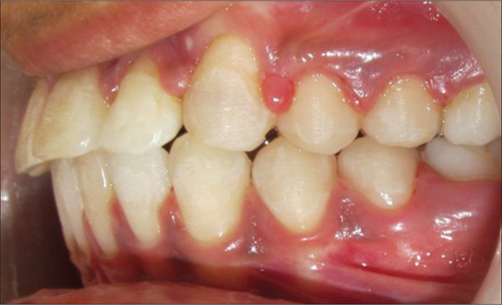
A buccally impacted canine is most commonly encountered and is usually positioned near the root of an adjacent tooth and mesial to its normal position [Figure 1].[1] One of the challenges of such vertical tooth movement is prevention of unwanted side effects on the molar.
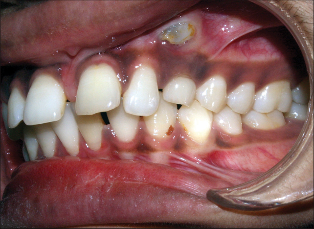
- Pretreatment intraoral left lateral photograph
Cantilever springs are simple and efficient orthodontic appliances, with a wide variety of clinical uses. Biomechanically, cantilevers are able to produce statically determinant force systems, giving the clinician the opportunity to deliver qualitatively and quantitatively precise forces.[2] A cantilever spring consists of 2 arms, the fixed and free end. The fixed end is inserted into a bracket or a tube, and the free end applies a point contact and does not engage a bracket slot or tube.
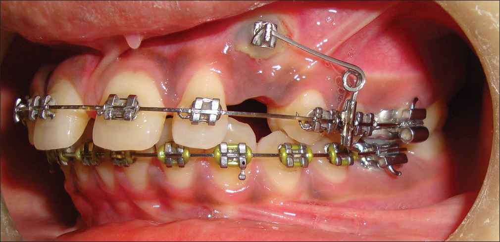
A 0.019” × 0.025” stainless steel archwire was placed in the maxillary arch, and a vertical tube was soldered to it between the premolars [Figure 2]. A 0.017” × 0.025” titanium-molybdenum alloy cantilever spring of 3 mm helix was fabricated with two arms [Figure 3]. The vertical arm, i.e., the fixed end of cantilever spring, was inserted into the soldered vertical tube and cinched [Figure 4], and the horizontal arm which is at 90° to the vertical arm was activated to in the incisal direction by closing the helix and forcefully engaging into the bracket bonded on the impacted canine [Figures 4 and 5]. This cantilever spring exerted 50 g of force for canine extrusion as measured with a force gauge [Figures 6 and 7].
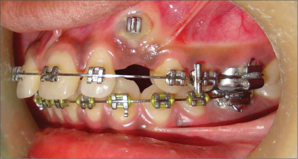
- 0.019” × 0.025” Stainless steel wire with soldered vertical tube
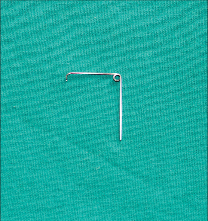
- 0.017” × 0.025” Titanium-molybdenum alloy cantilever spring (passive)
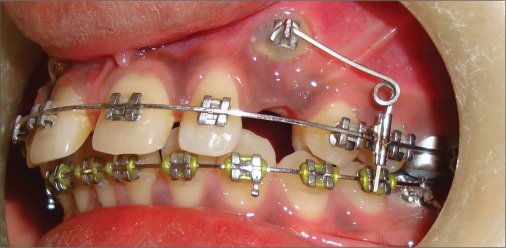
- Cantilever spring activation for canine extrusion
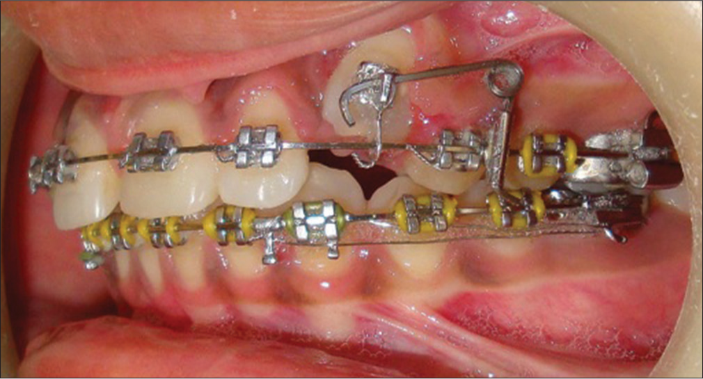
- The vertical arm of the cantilever spring cinched
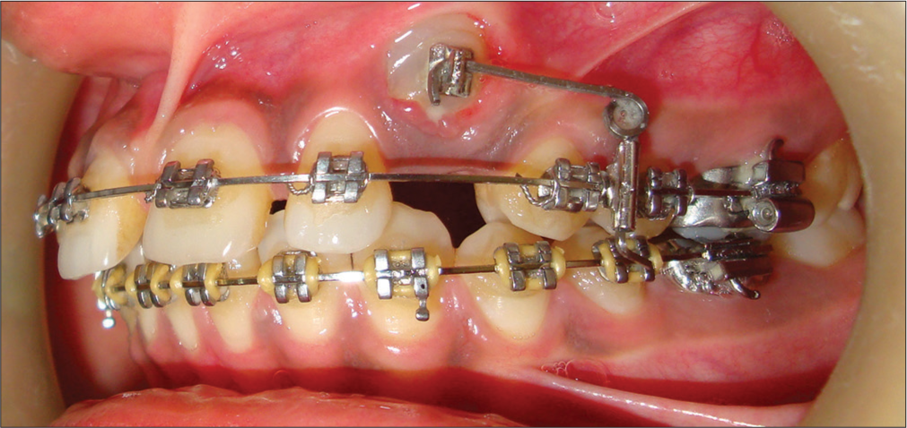
- Progress of canine extrusion over 2 months
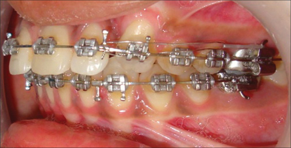
- Canine extrusion after 6 months of cantilever mechanics
This spring was shown to be an effective means of aligning buccally impacted maxillary canines [Figures 4 and 5]. Final alignment and leveling of canine was performed using 0.019” × 0.025” stainless steel wire. The residual space closure was done using active tie backs [Figure 8]. Post treatment intraoral photograph showing well aligned maxillary canine in the arch [Figure 9].
- Space closure with stainless steel base archwire after canine alignment
- Posttreatment intraoral left lateral photograph
This spring can be easily fabricated and activated at chair side for extrusion of a single tooth to avoid the unwanted effects on the molar and can also be used when an auxiliary molar tube is not available.
Financial support and sponsorship
Nil.
Conflicts of interest
There are no conflicts of interest.
References
- A cantilever spring for alignment of buccally impacted canines. J Clin Orthod. 2012;46:354-5.
- [Google Scholar]
- Cantilever springs: Force system and clinical applications. Semin Orthod. 2001;7:150-9.
- [Google Scholar]