Translate this page into:
Digital orthodontic indirect bonding systems: A new wave

*Corresponding author: Digant P. Thakkar, Silver Smile Orthodontics, Digant’s 3D Orthodontics, Rajkot, Gujarat, India. digantorthodontist@gmail.com
-
Received: ,
Accepted: ,
How to cite this article: Balut N, Thakkar DP, Gonzalez E, Eluani R, Silva LD. Digital orthodontic indirect bonding systems: A new wave. APOS Trends Orthod 2020;10(3):195-200.
Abstract
Digital technologies are progressing with leaps and bounds and the field of orthodontics is not untouched by it, with innovations like intraoral scanners and 3D printers being easy to own and maintain and increased availability of biocompatible 3D printing materials orthodontist are curious to use this technology to improve orthodontic bracket positioning which would require minimal to no repositioning during the course of treatment. The authors here have tried to outline 2 different methods using CBCT and VTO as guide to decide the bracket positioning digitally and using 3D printed Indirect Bonding trays for orthodontic bonding.
Keywords
Digital orthodontics
Indirect bonding
Digital indirect bonding
3D printing
Indirect bonding trays

Indirect bonding has been a well-established system for many years. Introduced by Silverman et al.,[1] it is a method that uses transfer trays made of compressed plastic to transfer the brackets placed on plaster models. IDS 2019 showed a significant surge in intraoral scanning and 3D printing technology, making it more accurate, efficiently, and widely available. Newer 3D printing materials were developed with dentistry, and especially orthodontics in mind, with emphasis on in-office 3D scanning and printing. Indirect bonding has many advantages, such as patient comfort, natural reproduction of bracket positioning, overcorrection, control of in and out movements of the teeth, and reduced treatment duration.[2]
This technique has been available for many years, but very few orthodontists use it, mainly because the laboratory and chairside procedures are lengthy and overly complicated, considering the manual fabrication of indirect bonding trays. With the amalgamation of digital technologies such as intraoral scanning and 3D printing in orthodontic laboratory workflow, one must explore the opportunities and ease these technologies bring to the indirect bonding technique.[3] The rising popularity of intraoral scanning has opened up new avenues for planning, designing, and executing orthodontic treatment for our patients.
The indirect bonding system was developed as a manual laboratory process.[4] It has been reported that a silicon-based tray has better precision compared to a thermoform tray.[5] At present, indirect bonding uses computer-aided design and computer-aided manufacturing (CAD/CAM). The CAD/CAM programs design a virtual model to produce a bracket transfer jig, and the CAD/CAM bracket transfer jig facilitates bonding of the bracket to the target tooth.[6-8] For instance, three-dimensional (3D) modeling of the maxilla and mandible can be used for the ideal setup and 3D printing of bracket transfer jigs. These would, subsequently, be involved in transferring brackets with individualized bracket positioning based on virtual treatment objective, custom resin bases, and proper arch forms by giving a complete picture of the treatment’s progress. Arch forms simplify chairside wire bending, custom resin bases simplify the requirement of the third order bends, and bracket transfer jigs help to position the brackets as per the digital planning accurately. Koo et al.[9] found that, on average, IDB was more accurate regarding bracket height, with no significant difference between IDB and direct bonding for angulation and mesiodistal position.
This article details the recent advances in digital indirect bonding using the Ortho-Analyzer software 3Shape and Onyx Ceph Software Image Insuruments, which includes digital planning, different tray designs, and in-house 3D printing, making it easy to incorporate in daily orthodontic practice.
CASE REPORT
Before the virtual placement of the brackets, the possibility of splicing DICOM/STL allows us you know and locate the exact axis of the roots and crowns, which has a direct effect on the expression of the prescription of the chosen system [Figure 1].
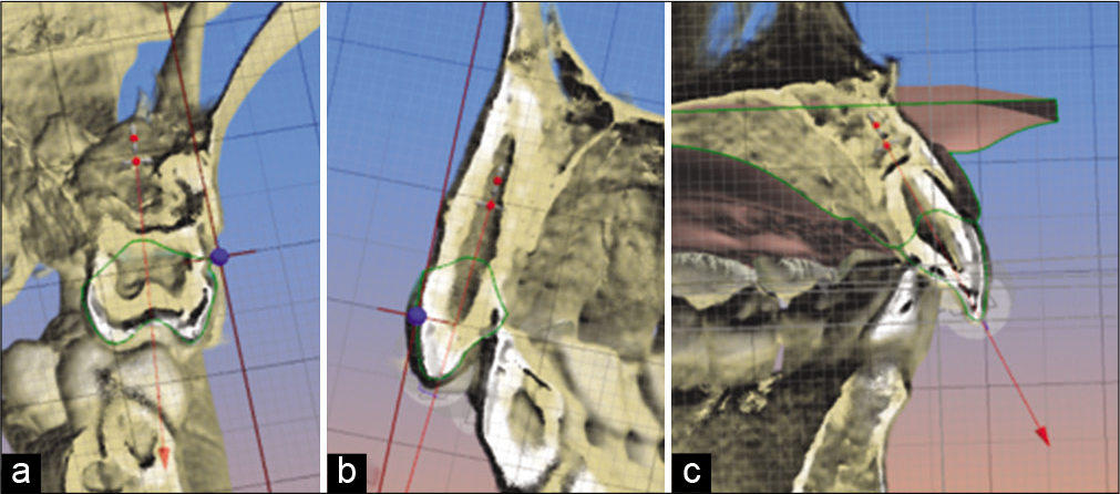
- (a) Location of the coronal-root axis, first upper molar, (b) position of the coronal-root axis, upper cuspid, (c) location of the coronal-root axis, upper central incisor.
Once the axial axes of the teeth and their own roots have been located, we proceed to place the virtual brackets [Figure 2]. It is important to emphasize that digital bonding can be done using any type of bracket, which allows any orthodontist to apply it in their office, regardless of the prescription of their choice.
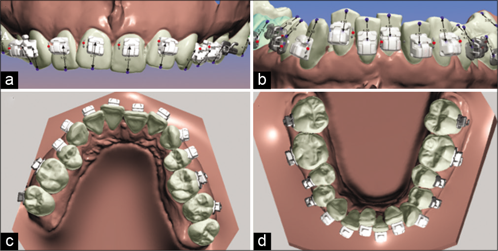
- (a) Position of the brackets in the model, upper incisors frontal view, (b) position of the brackets, lower incisors frontal view, (c) occlusal view of the brackets, position in the upper arch, (d) occlusal view of the brackets, position in the lower arch using the Ortho-Analyzer Software.
In this particular case, we use the bracket placement strategy proposed by doctors Nasib Balud and David Sarver.[10]
The position of the brackets is again evaluated on the tomography to make sure that the location coincides with the coronal-root axis [Figure 3].
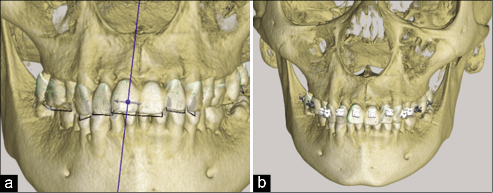
- (a) Location of axes in tomography, long axis of the tooth, (b) location of the brackets in tomography positioned with the long axis of the tooth.
The next step is to evaluate the splicing between the scan tomography, tubes, and brackets with the length of the axis of the tooth. These tools will help us assess the torque that will be applied to each tooth [Figure 4].
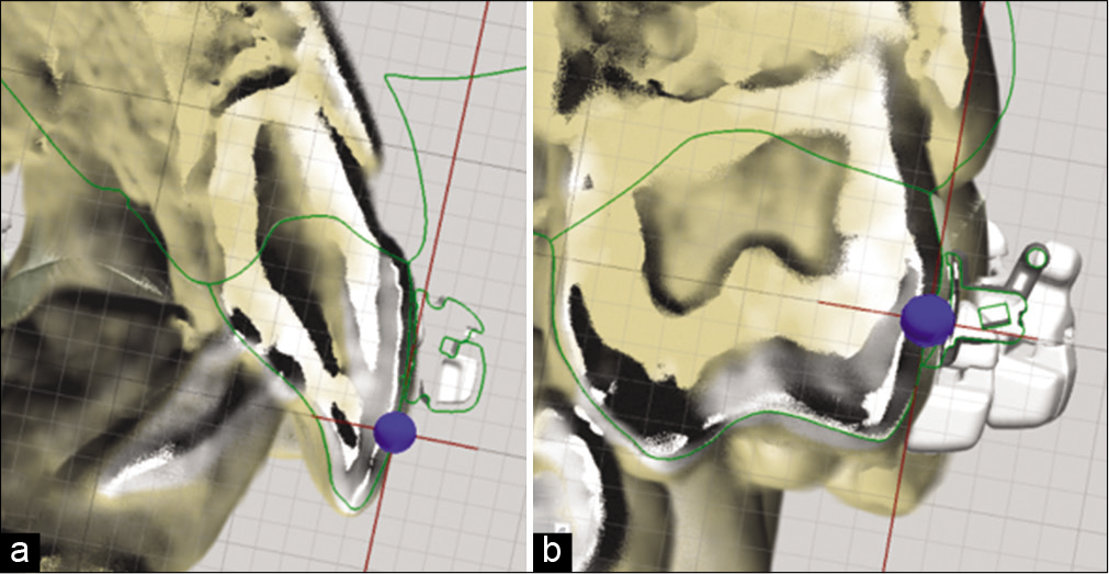
- (a) Splicing of the scan and tomography with the bracket for axe assessment, (b) splicing of the scan and tomography with a tube for axe evaluation.
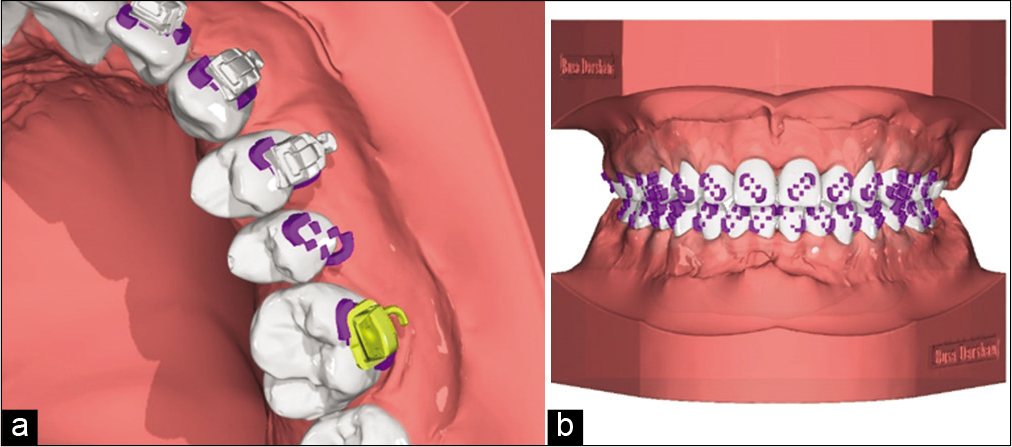
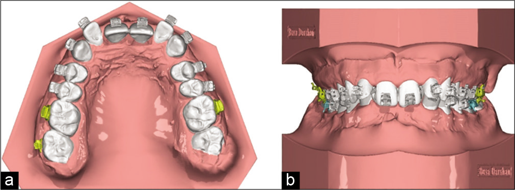
Once the position of the brackets meets the objectives of our treatment plan after reviewing it in detail, we prepare the model for the subsequent design of the guide. Such preparation consists of virtually eliminating the retention areas [Figure 5].
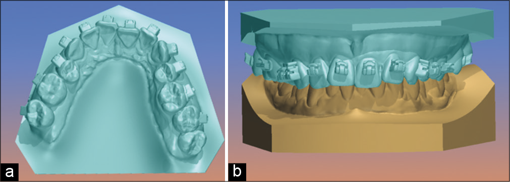
- (a) Upper model occlusal view, where we observe the virtual filling of retention areas such as bracket tubes and fins, (b) frontal view of the upper model with the lower arch.
Once the retentions are released, we will design the trays considering enough height to support brackets and tubes but being careful not to wrap them too much not to generate mechanical retention. To facilitate the removal of the guide after cementing the brackets, it is important not to include the hooks inside the guide and cover two-thirds of the bracket [Figure 6].
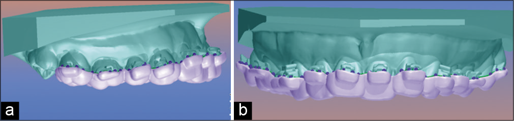
- (a) Guide design mounted on the upper model, lateral view, (b) guide design mounted on the upper model, frontal view.
The step after design is important to evaluate the precision of the guide in the model, which will help avoid errors when taking it to the patient’s mouth [Figure 7].
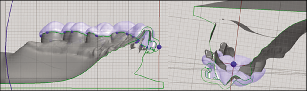
- Sagittal section of the scan including the virtual model, the brackets, and digital tube. Here, we are able the thickness and precision of the guide.
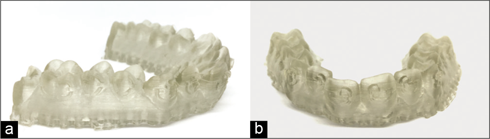
Once we evaluate the accuracy of the guard, it will be ready to be printed using a sufficiently flexible material so that it is not so retentive and can be easily removed after placing it. In this case, we used a printed acrylic resin the Digital Light Processing system [Figure 8].
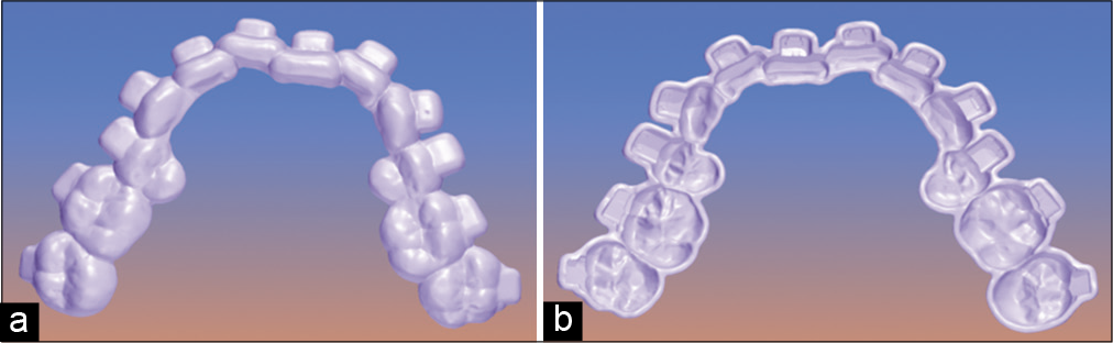
- (a) Digital upper guide finished, occlusal view, (b) digital upper guide finished, inside view.
Next, we place the selected brackets using the software and verify they fit perfectly in our guide design [Figure 9].
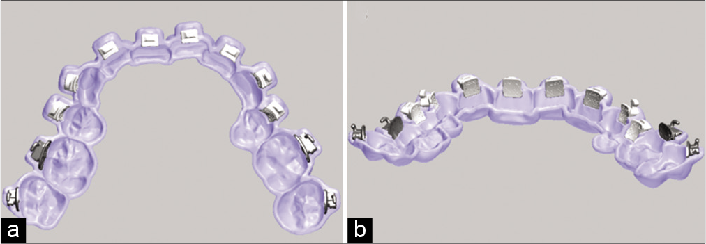
- (a) Digital upper guide with virtual brackets, inside view, (b) digital upper guide with virtual brackets, posteroanterior view.
If it is convenient for the case, the cemented guides can be digitally fragmented, which is very useful in cases of severe crowding [Figure 10].
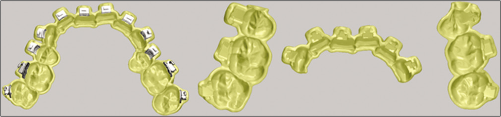
- Digital upper guide segmented into three parts.
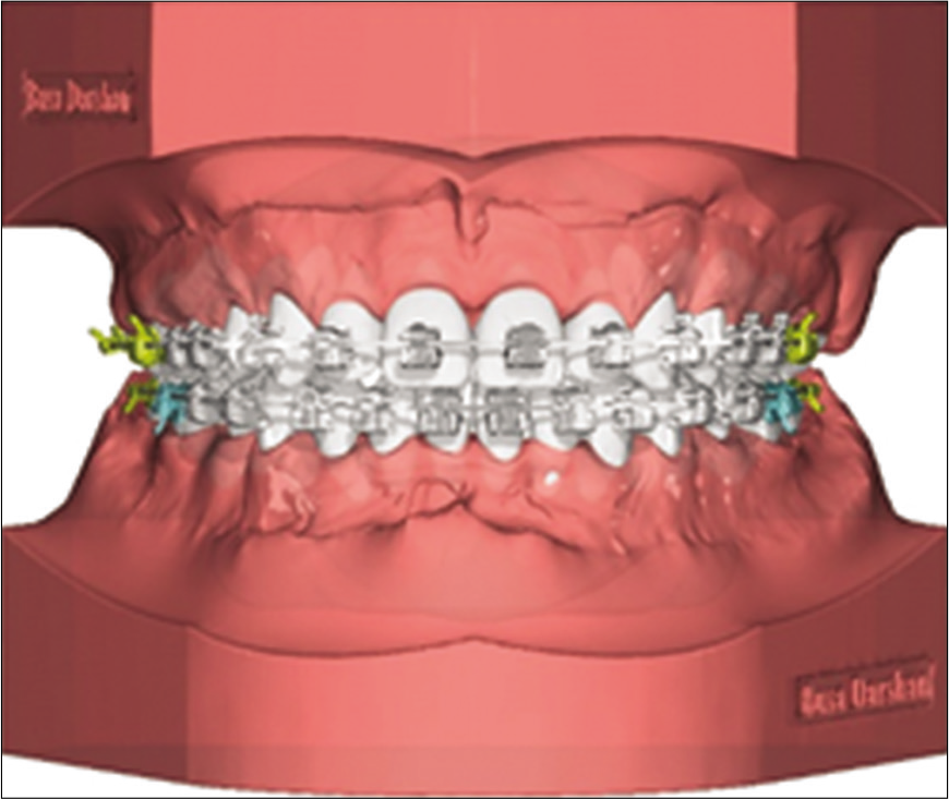
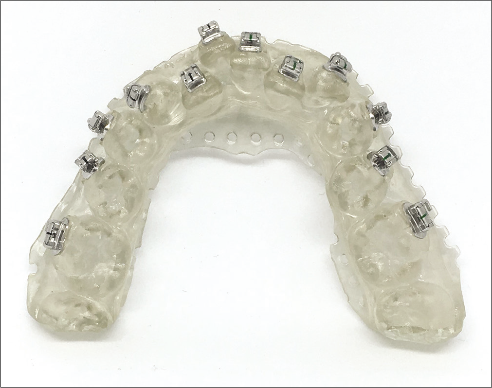
The next step is the physical impression of the guides and places the brackets in the patient’s mouth [Figure 11].
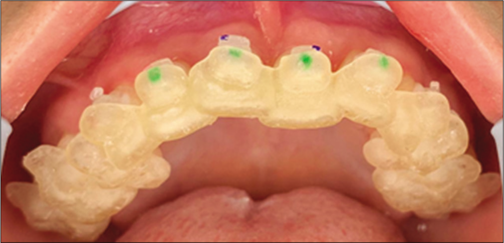
- Placement of brackets with complete upper guide.
As mentioned earlier, it was decided to segment the guide into three parts due to crowding in the lower arch [Figure 12].
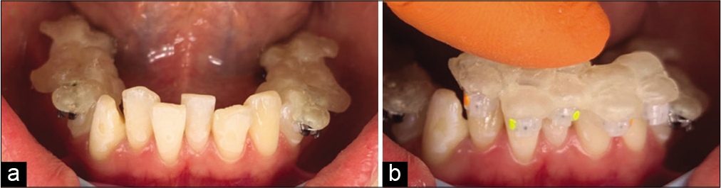
- (a) Placement of brackets with the segmented lower guide in molars and bicuspids, (b) placement of brackets with the segmented lower guide in cuspid and incisors.
Once all brackets have been placed and cured for 20 s each, the guide is removed. We must be careful to not remove any brackets in this step [Figure 13].
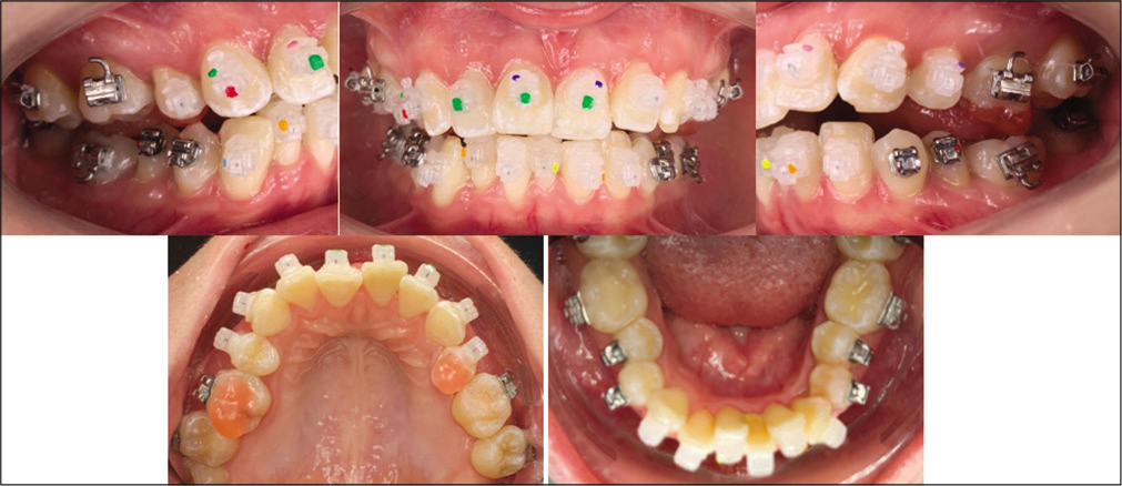
- Tray removed by teasing out with hemostat along gingivae above or below brackets and then rolling lingually.
SECOND METHOD CASE REPORT
After intraoral scanning, the scans are cleaned and digital base are constructed [Figure 14].
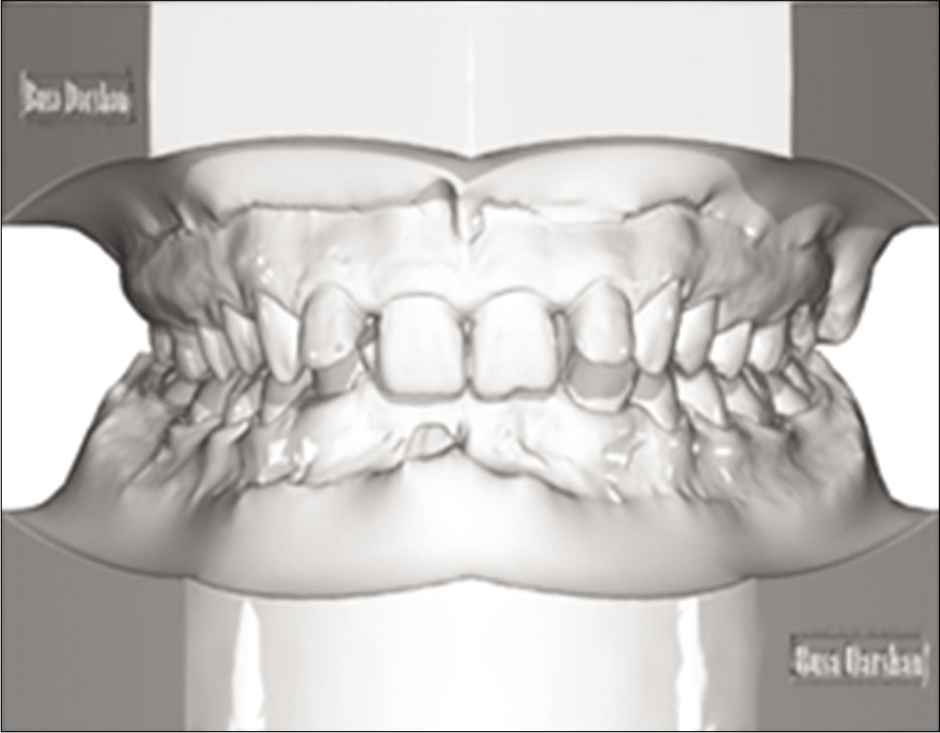
- Scan with digital base.
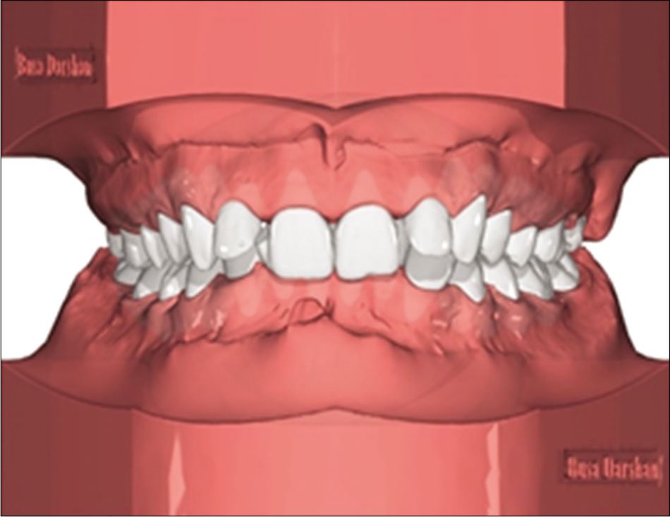
Individual tooth is digitally separated/segmented [Figure 15] and based on diagnosis by an orthodontists expertise using cephalometry and photographs as required a digital virtual tooth movements are constructed [Figure 16].
- Segmentation of individual tooth.
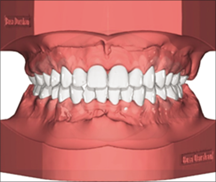
- Virtual treatment setup.
Based on the final tooth positioning brackets are positioned on individual teeth in a straight line, conceptualizing a true straight wire appliance [Figure 17].
- Individual bracket positioning by straight wire concept.
This bracket positioning compensates individual torque for each teeth which can be observed as distance between tooth and brackets, a torque compensation model is created to support these bracket distances which is used to make a composite base before bonding using 3D printed bonding trays [Figure 18a and b] these models are printed [Figure 19a and b] using DLP printers with 50 micorns accuracy.
- Torque compensation on individual bracket by digitally constructed base, (a) closeup view with and without brackets, (b) bracket support model ready for printing.
- Torque compensation models printed from fig 18, (a) lateral view, (b) frontal view
The bracket positing record on VTO model [Figure 17] is transferred to original malocclusion [Figure 20a and b]. Based on these brackets positioning digital indirect bonding trays are calculated similar to method 1, the bracket coverage is determined based on the type of 3D printing material used, flexibility of the bonding tray material in inversely proportional to the bracket coverage in the tray, i.e., stiffer the material less is bracket coverage.
- Bracket positioning based on VTO transferred to malocclusion (a) occlusal view , (b) Frontal view.
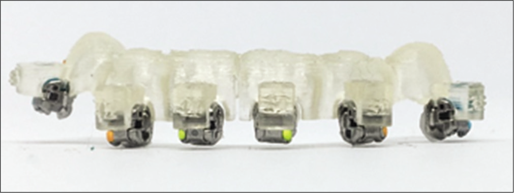
Once trays are printed, composite base is made using the 3D printed torque compensation models [Figure 21], these brackets are loaded in the indirect bonding trays. Bonding trays are segmented based on crowing and preferences of an orthodontist [Figure 22] a small segment of indirect bonding tray loaded with brackets can be seen in Figure 23.
- Orthodontic brackets bonded on Torque compensation.
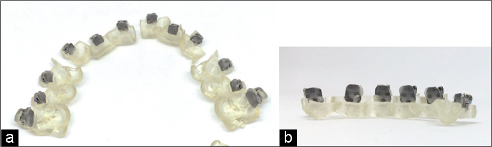
- Printed indirect bonding trays segmented in part for bonding.
CONCLUSION
Digital technology in progressing by leaps and bounds in field of orthodontics. One can use this technology in many different ways with sole purpose being simplifying the road toward quality orthodontic care for the patients. Digital planning with indirect bonding make orthodontist more efficient and accurate in terms of saving chair side time, having clear vision toward treatment progress and improving patient consults.
Declaration of patient consent
Patient’s consent not required as patients identity is not disclosed or compromised.
Financial support and sponsorship
Nil.
Conflicts of interest
There are no conflicts of interest.
References
- A universal direct bonding system for both metal and plastic brackets. Am J Orthod. 1972;62:236-44.
- [CrossRef] [Google Scholar]
- Indirect bonding: A comprehensive review of the advantages. World J Orthod. 2004;5:301-7.
- [Google Scholar]
- Digital technology for indirect bonding. Semin Orthodont. 2018;24:451-60.
- [CrossRef] [Google Scholar]
- Measurement and comparison of bracket transfer accuracy of Measurement and comparison of bracket transfer accuracy of five indirect bonding techniques. Angle Orthod. 2014;84:607-14.
- [CrossRef] [PubMed] [Google Scholar]
- The OrthoCAD bracket placement solution. Am J Orthod Dentofacial Orthop. 2004;125:645-6.
- [CrossRef] [PubMed] [Google Scholar]
- Comparison of the accuracy of bracket placement between direct and indirect bonding techniques. Am J Orthod Dentofacial Orthop. 1999;116:346-51.
- [CrossRef] [Google Scholar]
- Strategies for bracket placement based on smile esthetics. Am J Orthod. 2019;53:326-33.
- [Google Scholar]