Translate this page into:
Direct Printed Metal Devices - The Next Level of Computer-aided Design and Computer-aided Manufacturing Applications in the Orthodontic Care
Address for correspondence: Simon Graf, Smile AG (Smile Inc., Private Orthodontic Clinic), Belp, Switzerland. E-mail: info@smile-ag.ch
This article was originally published by Wolters Kluwer and was migrated to Scientific Scholar after the change of Publisher.
Abstract
As the whole world gets more digital, so do we. This article provides a basic know-how for the CAD/CAM-workflow for metallic orthodontic appliances. Demonstrating step-by-step how to design the appliance on a digital cast and laser-melting (3D metal printing) it, till the final result, without any physical models.
Keywords
Digital cast
digital orthodontic appliances
intraoral scanning
three-dimensional metal printing

[SHOW_RELATED_PUBMED_ARTICLES]
Introduction
Not many years ago, the orthodontists had to ask themselves, should we change from analog cameras to a digital one’s for records? The advantages such as immediate availability after taking the picture, storage and handling of digital pictures convinced them all.[1-3] The next obvious step was the digital X-ray, should we change? The same story happened in that case: Lower radiation, higher resolution of the X-ray, and less pollution of the environment due to less chemical developer use convinced the orthodontists.[4-6]
Besides this, the clinic setup changed from paperwork and analog patient-history to a computerized process in every aspect of the bureaucracy of the daily business, making the daily procedures in the clinic easier, quicker, and immediately available in every moment.[7,8] No more nurses running in the clinic, looking for patient-records, no more piles of paper at the end of the month which resulted in productivity and time for the important part in the clinic; the treatment of the patients.
Basic Equipment
This leads to the next step, the digital impressions. Should we scan or not? Nowadays, it is not the question about precision of the scan; the question is whether the orthodontic clinic and the cooperating dental lab are ready for it.[9]
So what is the aim for an intraoral scanner in the daily business of the clinic? Is it only for space analysis or to show a treatment outcome to the patients? Or is the goal to replace all the alginate or silicone impressions? Actually, does it make sense to have an intraoral scanner and still use alginate beside? When it is possible to have a bigger comfort for the patients (e.g., Gag-reflex), less storage space in the clinic and less pollution because of digital transmission of the data instead of sending the impressions by courier to the technician. Well to put it directly the advantages of scanning to the orthodontist beside the storage room are immediate disposability of the casts, reproducibility of the scan and direct check of the scan quality on the screen and in the mouth apart from the one’s mentioned earlier. Hence if there is a scan problem with the cast, it can be fixed immediately, instead of the feedback of the technician what leads to a new appointment for the patient for a new uncomfortable alginate impression.[10]
And is there maybe even the need for two scanners, if the clinic has more than two chairs?
Well some points to ponder before actually getting a scanner to your dental office should be thought about the use of an intraoral scanner, which scanner is the optimal one for your dental office? It takes some time to evaluate this point with the whole team, as they will probably scan more than the orthodontist himself.
The data output of the scan should be considered. The most common output is STL-files (stereolithographic files, or surface-tessellation-language), an open file with whom the most three-dimensional (3D)-software can work.
About the data output, will there be only a direct upload link to the technician, or should the 3D-data be available in the clinic network, is the clinic network prepared for this workflow with this amount of 3D-data are some of the other questions to be answered before getting an intraoral scanner.
As soon as, the clinic is ready, the orthodontist or the nurse in charge should train with the intraoral scanner as much as possible, to reach the best possible result in the shortest possible time.
It is not only a question about using as less time as possible but also about what the scan is needed for. The scan quality for space analysis only does not need the same perfection, as much as a scan for aligners or appliance fabrication on teeth or mini-implants.
Currently, it is possible with the scan to make the space analysis [Figure 1], perform a digital setup, either to plan and show the outcome to the patients, prepare an indirect bonding tray, plan the whole treatment with aligners, custom-made buccal and lingual bracket systems (e.g., Suresmile, Insignia or Incognito 3M) and Digital Smile Design for a perfect esthetic result matching the face.[11-13]
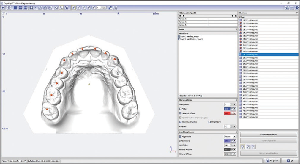
- Space analysis with onyxceph, image instruments, Chemnitz, Germany
What about removable and metal-based appliances? This will be the next step: Direct digital design and production of these appliances. At the moment, the dental technicians have to print the digital casts and produce the appliance the classic way.
Now, let’s change that!
Material and Methods
The intraoral scanner used for this way to produce the metallic orthodontic appliances was the Trios 2 from 3Shape (3Shape, Copenhagen, Denmark). Any intraoral scanner with an STL-file output can be used the same way.
After the scan of the arch for which the appliance is planned, the STL-file has to be imported in 3D-editing software. The specifications asked from the software are input of STL-files, design of 3D-designs with specific rules such as defined distances between designed or imported files and constancy of the thickness of the designed elements. The software used was the 3Shape appliance designer in this study.
The bonding sites need to be designed around the teeth in the shape of molar bands with the biggest possible bonding surface to the teeth on which the orthodontist want to have a bonding possibility. As the experience shows, it makes sense to have a small part produced thinner on the molar band as an emergency exit! Just in case the appliance does not come of, it’s easier to cut the molarband in this spot and de-bond it with a crown-spreader.
Another pearl to handle laser-sintered appliances is small de-bonding-spikes/buttons on the palatal and buccal surface to facilitate de-bonding!
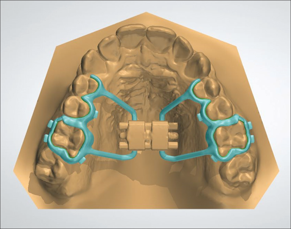
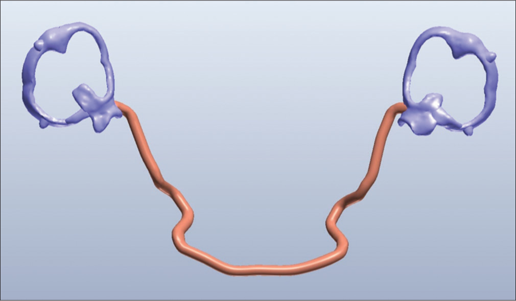
From these bands, connectors are designed along the teeth according to the need of the appliance. In the case of a lingual arch, two bands are designed around the molars and a round connector is designed along the lingual tooth surface [Figures 2 and 3]. Of course, there is no need to make the connector round, if wished, the connector can be designed perfectly fitting the lingual tooth surface.
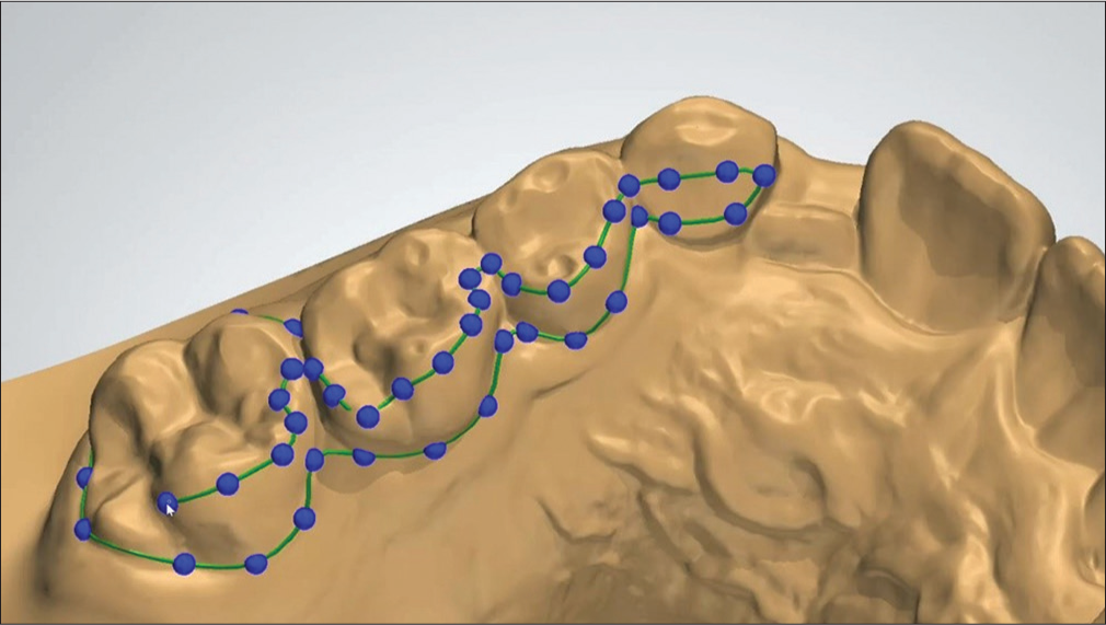
- Digital design of the surrounding of the bands along the teeth, 3Shape appliance designer, Copenhagen, Denmark

- Digital design of the bands along the teeth, 3Shape appliance designer, Copenhagen, Denmark
In the case of active appliances, the active elements have to be imported first into the software, and the appliances have to be designed around it. In the case of the hyrax (rapid palatal/maxillar expander), the expansion screw has to be scanned or digitally copied and positioned in the right place in the palate, so it will not touch the palate. If there is a coil-spring needed, for example, Frog-appliance, the spring can either be inserted in an active or passive state, depending on the demand of the treatment and orthodontist.
The 3D design will be sent to company with a laser-melting (3D-metal printing) device. The concept laser (Concept Laser, Hoffmann Innovation Group, Lichtenfels, Germany) was used in this study.
Now, the appliance will be sintered with Remanium® Star CL (Dentaurum, Ispringen, Germany), a metal alloy powder. This additive production builds the appliance layer by layer with this powder, which is locally melted with laser. After cooling down, the raw appliance has to be cleaned from the not melted powder and polished [Figures 4 and 5]. If there are active elements, the will be added with laser-welding and the bonding sites have to be sandblasted for an optimized attachment to the bonding material.

- Hyrax out of the laser melting unit

- Hyrax polished
The other available option is Rematitan® (Dentaurum, Ispringen, Germany), a titanium-based metal alloy in powder which can be used for additive production, but for finalization the process is more complex than for Remanium® Star CL and there is a higher level of security needed in the area of the sintering machines, as this powder-composition is highly reactive.
Of course, there is also the possibility to mill the basic structure of the appliance out of any solid metal, with the need of many burrs wasted. Nevertheless, the industrial trends direct to additive manufacturing and not to the substractive way.
The use of Remanium® Star CL led to some restrictions in the appliance design, as it is very stiff and rigid [Tables 1 and 2]. Hence, there are some rules from the partial dentures that have to be adapted for the molarband design. There can be no undercut below the equator of the tooth, otherwise, the appliance will not fit. An active element has to be inserted for every active movement, as the alloy cannot be bend and activated.
| Component | Mass (%) |
|---|---|
| Co | 60.5 |
| Cr | 28 |
| Tungsten | 9 |
| Si | 1.5 |
Other elements <1%: Mn, N, Nb, Fe free from nickel, beryllium and gallium
| Properties | Value |
|---|---|
| Yield strength | 635 MPa |
| Tensile strength | 1030 MPa |
| Elongation at fracture | 10% |
| Modulus of elasticity | 230.000 MPa |
| Melting range | 1320-1420°C |
| Density | 8.6 g/cm3 |
| Coefficient of thermal expansion | 14.1×10⁻⁶/K |
| Colour | White |
| Metal-ceramic bond strength | 40 MPa |
| Type | 5 |
| Biocompatibility | No deliberation of cell toxic active substances |
| Corrosion resistance | Ion release 3.5 ug/cm2×7 days |
The bonding procedure of these appliances are the same as used for the other appliances produced the classic way, either bonded or cemented, as it is up to the orthodontists preference.
Clinical Application
This production way can be applied for every metal based, as it is shown in three examples right away.
Hyrax (rapid palatal expansion)
The first step after scanning is to design the metal base of the appliance. Leave space for the connection to the expansion screw, for an optimal laser welding site. After sintering the screw is added to the appliance and fitted on the teeth with Transbond XT (3M).
Activation (Forestadent Snaplock Expander 12 mm screw, 0.9 mm per complete turn) twice per day for 2 weeks. Regular reaction on the hyrax is observed [Figures 6-11].
- Digital design of the hyrax

- Check of the laser welding sites for the expansion screw
- Before insertion of the hyrax

- Hyrax in situ

- One-week activation

- Two weeks activation
Trans palatal arch
The same approach is done with a classic transpalatal arch (TPA). In this case the bonding site is designed on the molars not completelly circular, but only palatal. This design allows an immediate start of a fully fixed treatment. Retraction and alignment of the canine, final torque of the lateral incisor and retention with a bonded retainer [Figures 12-16].
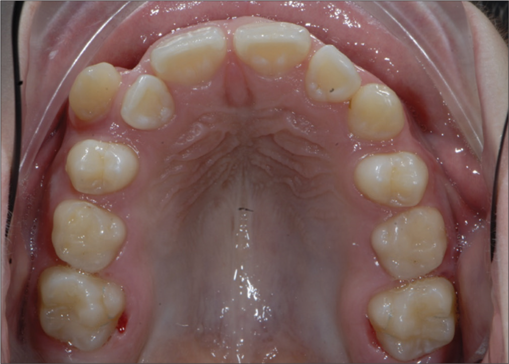
- Before insertion of the trans palatal arch
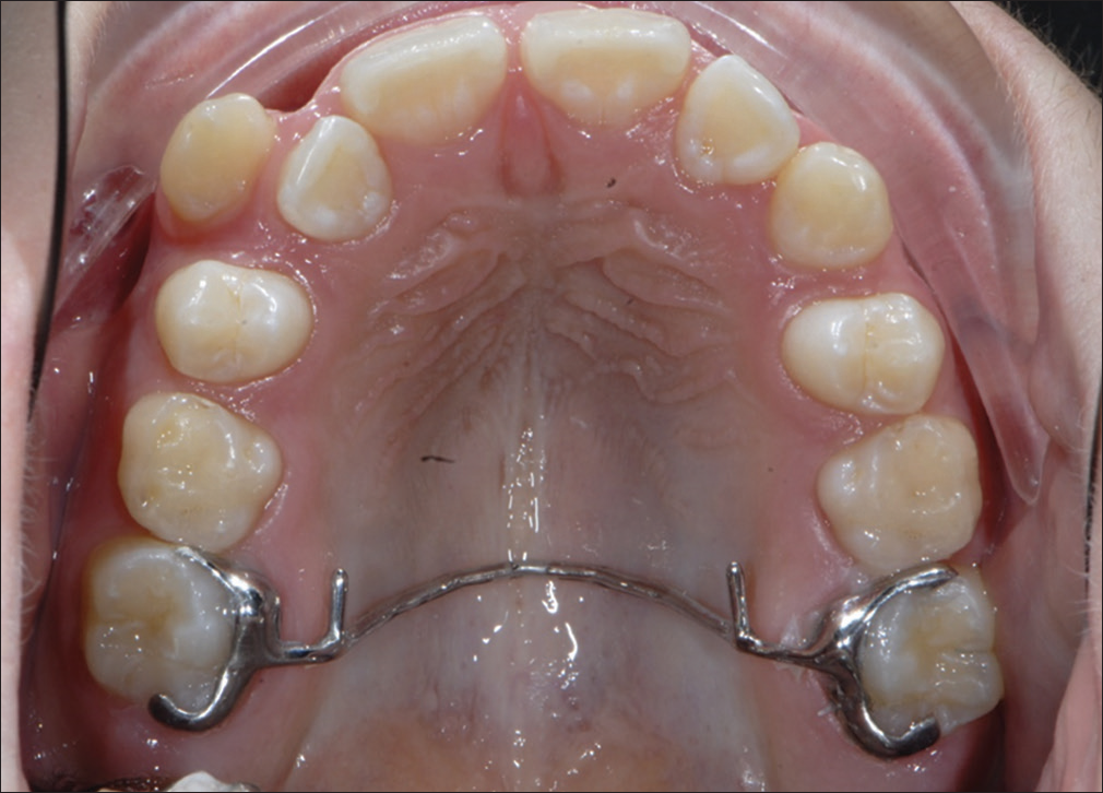
- Trans palatal arch in situ
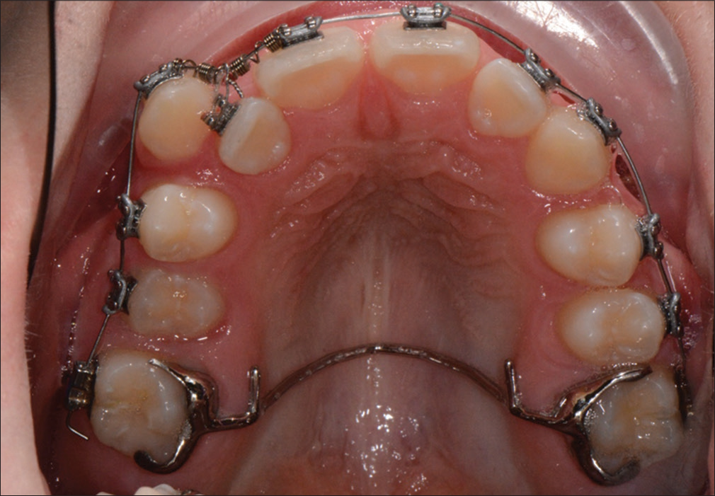
- Begin of active treatment with fixed multibracket appliance
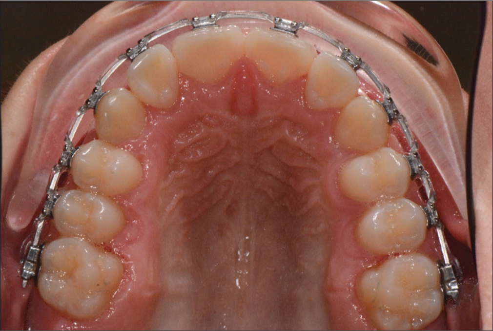
- After removal of the trans palatal arch

- Final with bonded retainer
If there is a need of a de-rotating force on the molar, it is urgent to remember the properties of Remanium Star - > no activation possible. In this case, it is possible to replace a part (or the complete) of the connector between the molars with a springy wire (e.g., NiTi alloy wire). Otherwise, it is possible to laser sinter the TPA with Rematitan and a longer connector, for a better force distribution when activating it.
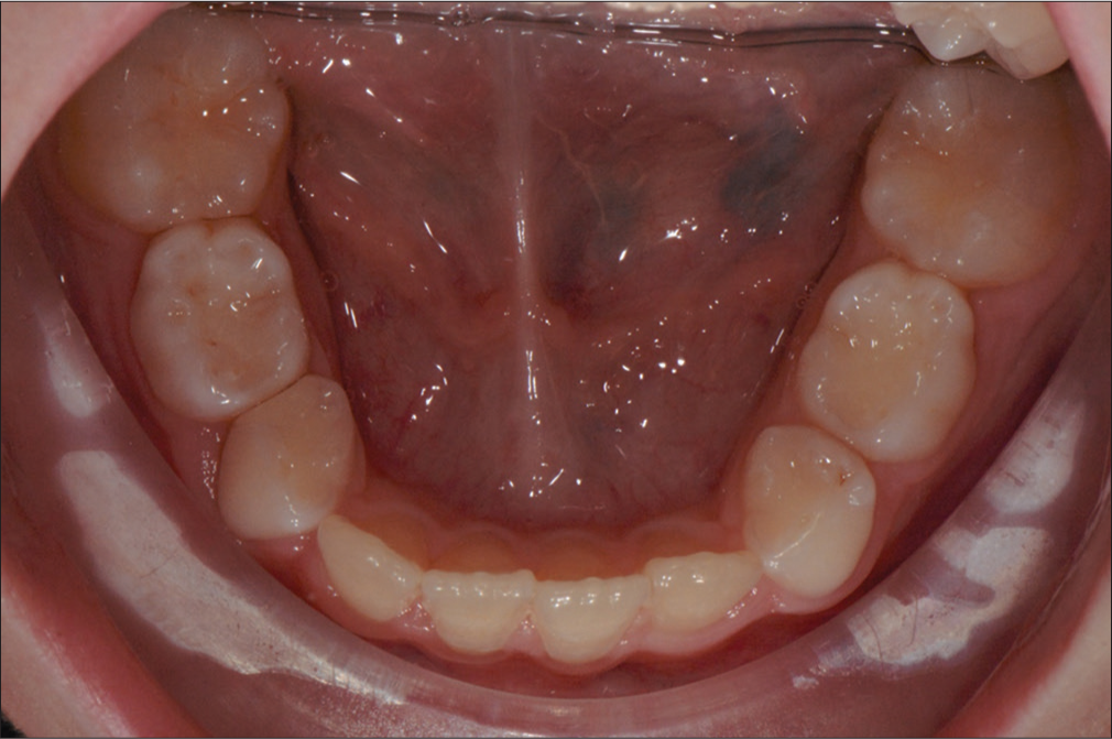
Lingual arch
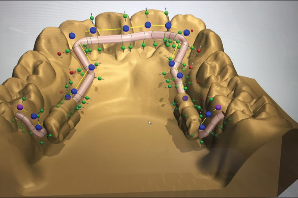
Let’s go to the lower arch. For a lingual arch, bands are designed (fully or partial) around the molars. Then a connector is designed along the lingual surface of the teeth, connecting tooth 36 and 46. The position in the question of height, close to incisal edge or gingiva, is up to the orthodontist. Furthermore, space can be left for teeth that will erupt shortly. The activation bend was designed because of nostalgic reasons, as there is no way to actually activate this material [Figures 17 and 19].

- Design of the molar band for the lingual arch
- Design of the complete lingual arch
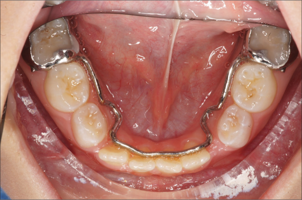
- Passive lingual arch in situ
In a case of space gaining, not only preventing, it is possible to ad expansion screw and activate them once every two weeks (Forestadent, Slim-Line 8 mm, 0.2 mm/turn). Otherwise, the connector can be laser welded from another alloy. In addition, sintering with Rematitan could be a solution in these cases [Figures 20-25].
- Design of the active lingual arch with distalisation screws
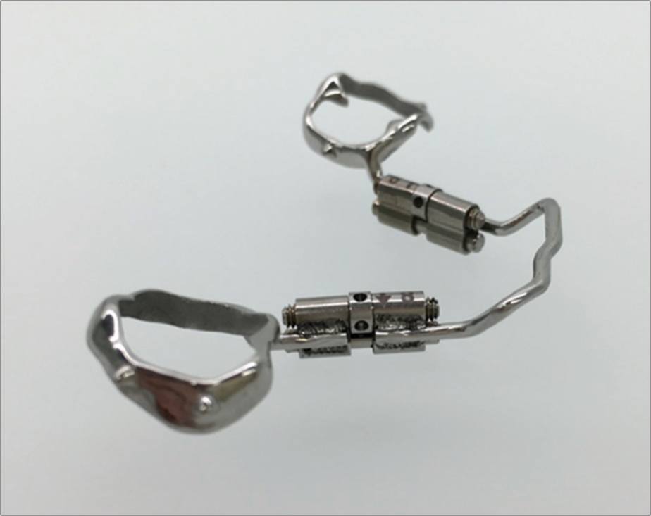
- Active lingual arch
- Before insertion of the active lingual arch

- Active lingual arch in situ
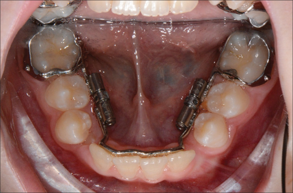
- Activation phase, eruption of permanent teeth
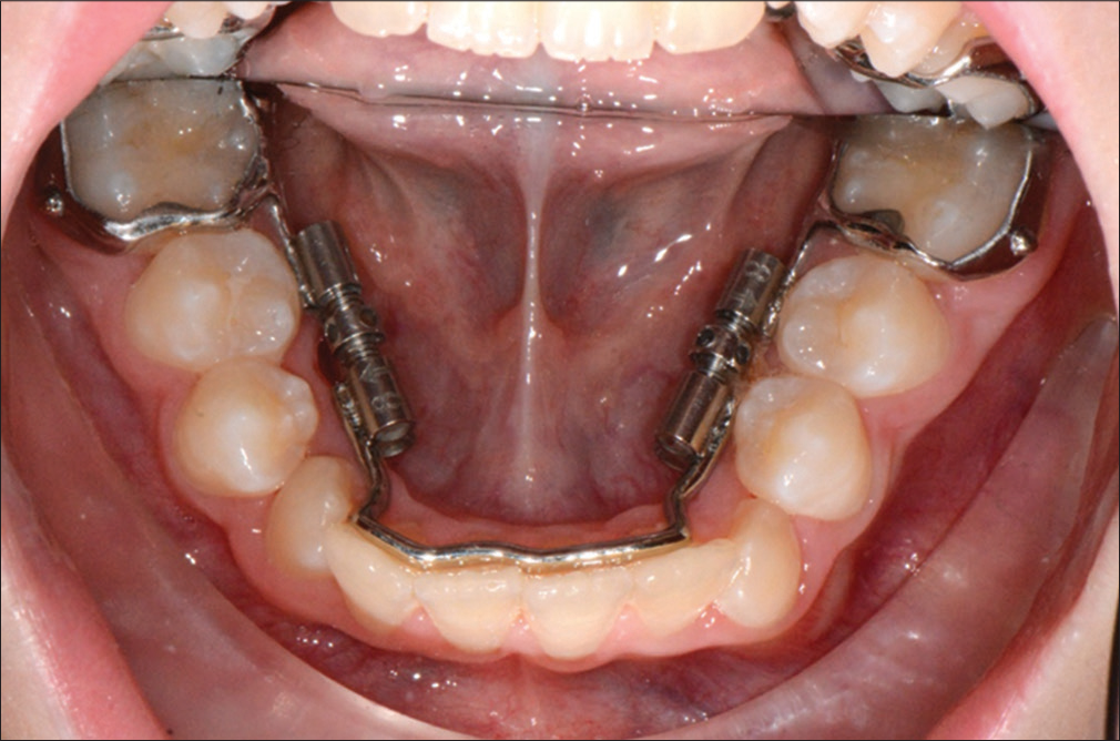
- End of activation and tooth change
Discussion
At the beginning, there was the discussion if the clinic and the dental lab are ready for the complete digital way? Yes they are, it is all here and ready to use!
Now the only question is, if every technician needs a laser melting device, or if there will be production centres and the dental technician just provides the design, or even the orthodontist himself. Hence, the costs for these machines can be split. The same question about the different software needed with its updates and annual license fee.
To choose the right design, strength of connectors and the different parts of these appliances, it is still a huge area to explore, as there is a huge potential in these way of producing orthodontic appliances.
Every new printable alloy will offer new ways and better handling, faster and more precise production.
All of the common appliances are adaptable somehow in the digital world; someone just needs to do the first step. Watch out for the next one with adding skeletal anchorage, scanning of the mini pins and direct printing of bone-borne appliances.
Also for removable appliances, there is a lot going on, as Food and Drug Administration approved printable acrylics are available on the market by now.
With establishing of 3D-printing and metal-printing, the range of different appliances will rise, the prices for the machines and appliances will drop and sooner or later replace the nowadays production.
Conclusion
The advantages of the last step in digitizing the orthodontic clinic will convince all orthodontist, even though it will take some time till all the clinics will be equipped with scanners. Furthermore, there are more appliances, bonded and removable, that have to be adapted first the digital way.
Financial support and sponsorship
Nil.
Conflicts of interest
There are no conflicts of interest.
References
- Enhancing interprofessional communication through digital photography. J Calif Dent Assoc. 2001;29:752-7.
- [Google Scholar]
- Comparison of landmark identification in traditional versus computer-aided digital cephalometry. Angle Orthod. 2000;70:387-92.
- [Google Scholar]
- The effects of differences in landmark identification on the cephalometric measurements in traditional versus digitized cephalometry. Angle Orthod. 2004;74:155-61.
- [Google Scholar]
- Filmless imaging: The uses of digital radiography in dental practice. J Am Dent Assoc. 2005;136:1379-87.
- [Google Scholar]
- Digital workflows in contemporary orthodontics. APOS Trends Orthod. 2017;7:12-8.
- [CrossRef] [Google Scholar]
- Full arch scans: Conventional versus digital impressions – An in-vitro study. Int J Comput Dent. 2011;14:11-21.
- [Google Scholar]
- Validity, reliability, and reproducibility of the IOC intraoral scanner: A comparison of tooth widths and Bolton ratios. Am J Orthod Dentofacial Orthop. 2013;144:304-10.
- [Google Scholar]
- Comparison of space analysis evaluations with digital models and plaster dental casts. Am J Orthod Dentofacial Orthop. 2009;136:16.e1-4.
- [Google Scholar]
- Orthodontic measurements on digital study models compared with plaster models: A systematic review. Orthod Craniofac Res. 2011;14:1-6.
- [Google Scholar]
- Accuracy of three dimensional cone beam computed tomography digital model measurements compared with plaster study casts. APOS Trends Orthod. 2017;7:215-8.
- [CrossRef] [Google Scholar]