Translate this page into:
Efficacy of transpalatal arch as an anchorage reinforcing unit during orthodontic space closure: A three-dimensional finite element study
Address for Correspondence: Dr. Vishal Shrishail Kudagi, Department of Orthodontics, JSS Dental College and Hospital, Mysore - 570 015, Karnataka, India. E-mail: drvishalsk@yahoo.com
This article was originally published by Wolters Kluwer and was migrated to Scientific Scholar after the change of Publisher.
Abstract
Background and Objectives
Connecting the contralateral upper molars by means of a transpalatal arch (TPA) is thought to decrease the tendency of the molars to move mesially in response to orthodontic force (i.e., provide orthodontic anchorage). This study was hence conducted to investigate the effects of the TPA on the displacement of the molars and stresses generated in the periodontium during orthodontic tooth movement using the finite element method (FEM).
Materials and Methods
A three-dimensional (3D) model was generated using medical modeling software (Mimics) using the computed tomography slice images of the skull which were obtained at a slice thickness of 1 mm. From this, the finite element model was built using HyperMesh and analysis was performed using PATRAN software (MSC Software Corporation, 4675 MacArthur Court, Newport Beach, California 92660). The 3D finite element models were fabricated in two versions such as maxillary first molars including their associated periodontal ligament and alveolar bone one with TPA and another without TPA. Both were subjected to orthodontic forces, and the resultant stress patterns and displacements between the models with and without TPA were determined.
Results
The stress and displacement plots in this study failed to show any significant differences in stress and displacement within the periodontium of molars, between the two models – one with TPA and the other without, in response to the orthodontic force.
Interpretation and Conclusion
The results of the current finite element analysis, therefore, suggest that the presence of a TPA brings about no change in the initial dental and periodontal stress distribution and displacement.
Keywords
Anchorage
finite element method
space closure
transpalatal arch
INTRODUCTION
Ever since its introduction by Dr. Robert A. Goshgarian in the year 1972, the transpalatal arch (TPA) and its modified versions have been applied widely in clinical orthodontics. One such application is to increase the resistance of molars to unwanted movement or in other words to provide orthodontic anchorage.[1] It is hypothesized that the TPA by splinting the two molars prevents their movement and thus reinforces anchorage.[2] Since anchorage is related to periodontal stresses and strains, the TPA must also be modifying these parameters around the molars and surrounding tissues. It is virtually impossible to quantify or detect these stress distribution patterns within the human periodontium accurately by in vivo methods.[3] However, mathematical methods which replicate the biological system accurately in both anatomy and physical characteristics such as the finite element method (FEM) are available in engineering, which can be applied to orthodontics as well.[4-6]
Finite element analysis (FEA) is the mathematical method in which the shape of complex geometric objects and their physical properties are modeled using a computer software. Physical interactions of various components of the model are then calculated in terms of stresses, strains, and deformation.[5,6] Over the past few years, FEA has been used to simulate various orthodontic scenarios and to quantify stress, strain, and displacement patterns of pertinent tissues (e.g., dental roots, the periodontal ligament, and alveolar bone).
Objectives
To construct two appropriate, three-dimensional (3D) finite element models of the maxillary first molars with their associated periodontal ligament and alveolar bone-one with TPA and another without TPA and to determine the resultant stress patterns in periodontium and displacement of molars with orthodontic force application in both models.
MATERIALS AND METHODS
Steps involved in this study using FEA were as follows:
Construction of geometric model
Assigning material properties
Defining the boundary conditions
Application of forces and
Analysis and interpretation of results.
Construction of geometric model
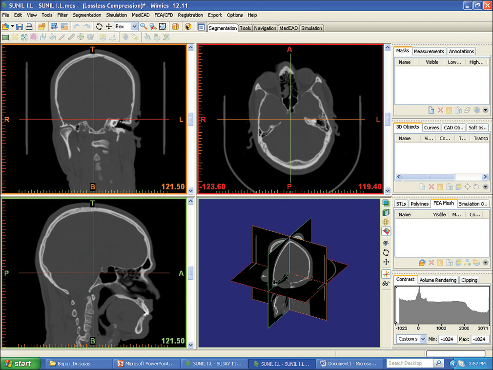
Computed tomography (CT) slice images of the skull of a cadaver were obtained at a slice thickness of 1 mm [Figures 1-3]. The FEA model was then created in two broad steps of generation of 3D model using the CT slices in a medical modeling software Mimics [Figure 4], and conversion of 3D model into the finite element model using CAD through the preprocessor software Altair HyperMesh (Altair Engineering, Troy, Michigan) [Figures 5-7]. Nastran was the solver used to perform the analysis in the present study.

- Importing of two-dimensional format computed tomography data to Mimics medical modeling software
- Selection of slices of interest to generate three-dimensional model
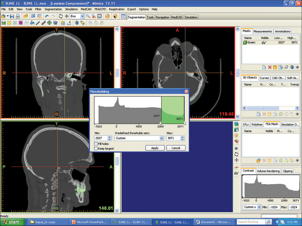
- Thresholding to separate teeth from full-face three-dimensional model
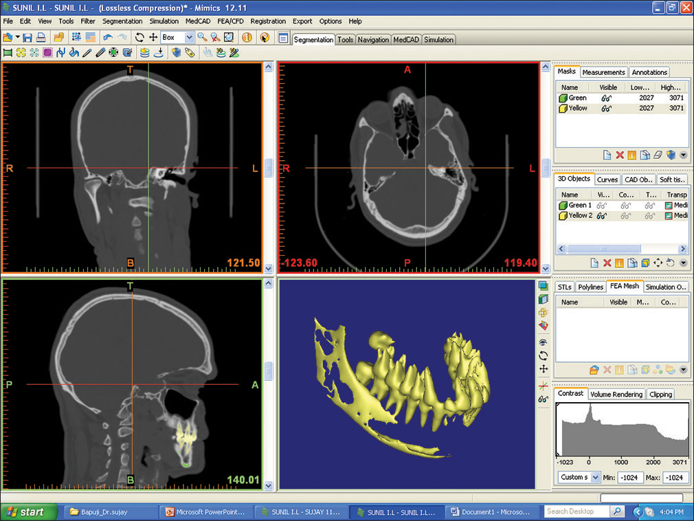
- Separation of teeth from rest of the three-dimensional model

- Remeshing and triangular reduction of the model

- Final three-dimensional molar models after cropping objects other than area of interest

- Final three-dimensional model with molars with transpalatal arch, including periodontium and alveolar bone around it
Two types of models were generated for comparative investigation:
Model 1: Consisting of maxillary first molars, their associated periodontal ligament, and alveolar bone segments with TPA [Figure 8]
 Figure 8
- Geometric model of maxillary first molars and its associated periodontium and alveolar bone segments, with transpalatal arch
Model 2: Consisting of maxillary first molars, their associated periodontal ligament, and alveolar bone segments without the TPA [Figure 9].
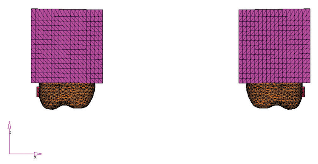 Figure 9
- Geometric model of maxillary first molars and its associated periodontium and alveolar bone segments without the transpalatal arch
Solid tetra elements were used to model the teeth, periodontium, bone, and TPA [Figure 7], which had three degrees of freedom (translation) at each node. TPA with Blue Elgiloy (0.9 mm diameter) wire was also modeled with tetra elements. The entire model comprised a total of 172,236 elements and 31,868 nodes.
Assigning material properties
The assignment of proper material properties to a FEM is necessary to simulate the behavior of the object being studied. The material properties assigned were the Young’s modulus (or modulus of elasticity) and the Poisson’s ratio – both derived from literature review [Table 1].[6-19]
| Material | Young’s modulus (GPa) | Poisson’s ratio |
|---|---|---|
| Enamel | 65 | 0.32 |
| Dentin | 15 | 0.28 |
| Periodontal ligament | 0.1 | 0.45 |
| Alveolar bone | 10 | 0.33 |
| Stainless steel | 170 | 0.3 |
| Elgiloy blue | 175 | 0.3 |
Defining the boundary conditions
The boundary conditions in FE models basically represent the load imposed on the structures under study and the area of the model which is restrained. In this study, the model was restrained from free body displacement by fixing the nodes at the superior border of the model [Figure 10].
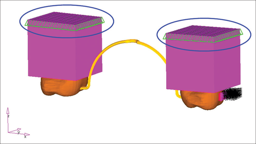
- Setting the boundary conditions for the model
Application of forces
Force of the magnitude 1 N (102 g) was applied on the buccal attachment of each molar band simultaneously, analogous to that seen clinically, when Class I elastics are used to create a distal force on anterior teeth during space closure [Figure 11].
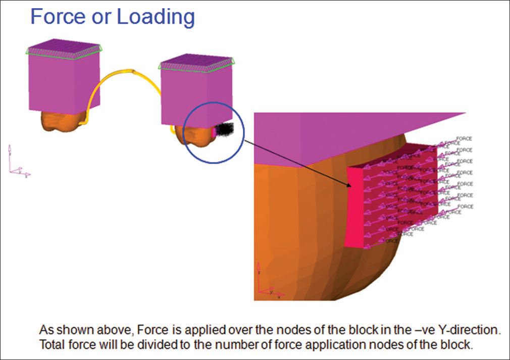
- Simulation of orthodontic force application on the model
Analysis and interpretation of results
A linear static evaluation was carried out. The model was divided into two cases. Case 1 comprised both models for which resultant stresses were calculated at nodes in response to force of 1 N magnitude and in case 2 the resultant displacements were calculated at the nodes for both models. The stress and displacements were determined at mesial, distal, and occlusogingival levels. They are presented in colorful contour bands, where different colors represent different stress levels in the deformed state. Positive and negative values in the column of stress spectrum indicate tension and compression, respectively. Results were expressed in stresses and displacements as follows:
Case 1: Stress plots of model with and without TPA and their periodontium when subjected to a force of 1 N [Table 2]
Table 2 Cases analysis summaryNumber Transpalatal arch Stress or displacement calculation position in response to 1 N of force 1 Model with TPA Stress at node (molar) 2 Model without TPA Stress at node (molar) 3 Model with TPA Stress at node (PDL) 4 Model without TPA Stress at node (PDL) 5 Model with TPA Displacement at node 6 Model without TPA Displacement at node TPA – Transpalatal arch; PDL – Periodontal ligament
Case 2: Deformation plots of model with and without TPA when subjected to a force of 1 N [Table 2].
RESULTS
To simplify the results, calculations were performed from maximum amount of stresses and displacements in each model. Qualitatively in Figures 12-17, the plots reveal patterns consisting of areas of positive and negative stresses located on the tooth and periodontal ligament, corresponding to areas of tension and compression, respectively. Stress magnitudes were denoted by a series of colors as shown in the spectrum display to the left of the stress plot. In general, yellow–red represent progressively greater tensile stress values, whereas the green–blue represent progressively greater magnitudes of compression.

- Stress plot for the molar in model with transpalatal arch

- Stress plot for the molar in model without transpalatal arch

- Stress plot for the periodontium in model with transpalatal arch

- Stress plot for the periodontium in model without transpalatal arch

- Displacement plot for model with transpalatal arch

- Displacement plot for model without transpalatal arch
The following results were observed:
Case 1 (Stress at Nodes): Figures 12 and 13 show that maximum stresses of 0.2578 MPa were associated with both models where forces of 1N were applied in the area of molar tube. Similarly, in Figures 14 and 15 maximum stresses of 1.083 E-02 MPa in periodontium of both models, with and without TPA, were seen [Tables 3 and 4].
Table 3 Maximum stresses generated at molar tube on force application in both modelsForce value (in N) Model with TPA (stress in MPa on the molar) Model without TPA (stress in MPa on the molar) Difference 1 0.2578 0.2578 Nil TPA – Transpalatal arch
Table 4 Maximum stresses generated in periodontium on force application in both modelsForce value (in N) Model with TPA (stress in MPa in PDL) Model without TPA (stress in MPa in PDL) Difference 1 0.01083 0.01083 Nil TPA – Transpalatal arch; PDL – Periodontal ligament
Case 2 (Displacement at Nodes): Figures 16 and 17 show maximum displacement of − 0.000149 mm associated with both models in the area of molar tube, where the forces of 1N were applied [Table 5].
Table 5 Maximum displacement associated with both models in the area of molar tubeForce value (in N) Model with TPA (displacement in mm) Model without TPA (displacement in mm) Difference 1 −0.000149 −0.000149 Nil TPA – Transpalatal arch
DISCUSSION
The current study has used the FEM of analysis to investigate the effectiveness of the use of the Blue Elgiloy TPA by quantifying the stresses generated in the periodontium-the physical property on which anchorage is thought to be dependent. From the analysis (of case 1–2) of the stress and displacement values of the two models, the presence of a TPA did not bring about any significant difference in stress distribution or displacement of the molars in response to the forces applied. In other words, in all the cases the maximum difference between any of the principal stresses between cases with and without a TPA was zero. If one accepts the belief that orthodontic anchorage is based on periodontal stresses, then the current results suggest that the TPA virtually has no effect on anchorage in the initial stages of the tooth movement.
The current analysis was not time-dependent. The results, therefore, may only be applicable to the initial stages of the tooth movement. With respect to the described limitations, the general validity, in terms of physical properties, model geometry, and element shape, of the current model was sufficiently enough to provide insight into the interactions of orthodontic forces, tissues, and appliances related to this investigation.[10,17] The results of the present study were in accordance with the studies done by Kojima and Fukui who also found that in orthodontic movement, the TPA had almost no effect in preserving anchorage for mesial movement.[6] However, the TPA prevented rotational, transverse, and vertical movements of the anchor teeth. [7,9,11,15,18] Our results were also similar to those in the study carried out by Zablocki et al. who concluded that the TPA does not provide a significant effect on either the anterioposterior or the vertical position of the maxillary first molar during extraction treatment.[8] Kojima et al. also found that the presence of a TPA had no effect on molar tipping, but it did decrease molar rotations and affected periodontal stress magnitude by <1%.[6]
CONCLUSION
This investigation was carried out to examine the effects of the TPA on stress patterns and displacements and the findings are as follows:
The stress plots failed to show any significant difference in the effects due to the presence of a TPA on the area of highest stress in both models
The displacement plots also failed to show any significant differences in the area of maximum displacement in both models in response to the applied orthodontic force.
The results of the current FEA, therefore, suggest that the presence of a TPA brings about no changes in the dental and periodontal stress distributions.
Acknowledgment
It is with a lot of gratitude that I thank my guide, Professor, Dr. N. Vijay for having guided me through my postgraduate course and also the tumultuous phase of preparing my thesis. Without your kind guidance, my thesis would never have achieved the state that it has today. Thank you sir. It is indeed a privilege to have done my postgraduate course under Dr. K. Sadashiva Shetty. Very few are as blessed as I am. Learning under you was a most profound and wonderful experience. The memories that I relate to most strongly is of your fondness for perfection. Not just in orthodontics but in everything in life. Truly, it is only due to your perseverance that we stand with our heads held high today. Thank you very much sir. I am heartily thankful to my co-guide Dr. H. C. Kiran Kumar whose encouragement, guidance, and support from the initial to the final level enabled me to develop an understanding of the subject. My sincere thanks to the staff members Dr. E. T. Roy, Dr. Sunil Sunny, Dr. M. S. V. Kishore, Dr. A. T. Prakash, Dr. Anisha Manjeni, Dr. Shravan Kumar, and Dr. Deepthi for being my wheel of support and encouragement during the course. I am very grateful to Mr. Nirguna Joshi for carrying out the engineering work.
Financial support and sponsorship
Nil.
Conflicts of interest
There are no conflicts of interest.
References
- Clinical use of custom made transpalatal arches-why and how. Ask an expert. World J Orthod. 2004;5:260-7.
- [Google Scholar]
- Contemporary Orthodontics. St. Louis: CV Mosby; 1986.
- Moments and forces delivered by transpalatal arches for symmetrical first molar rotation. Eur J Orthod. 1996;18:131-9.
- [CrossRef] [PubMed] [Google Scholar]
- Three-dimensional finite element analysis for stress in the periodontal tissue by orthodontic forces. Am J Orthod Dentofacial Orthop. 1987;92:499-505.
- [CrossRef] [Google Scholar]
- Stress-related molar responses to the transpalatal arch: A finite element analysis. Am J Orthod Dentofacial Orthop. 1997;112:512-8.
- [Google Scholar]
- Effects of transpalatal arch on molar movement produced by mesial force: A finite element simulation. Am J Orthod Dentofacial Orthop. 2008;134:335.e1-7.
- [CrossRef] [Google Scholar]
- Optimization of unilateral molar rotation correction by a trans-palatal bar: A three-dimensional analysis using the finite element method. J Orthod. 2013;40:197-205.
- [CrossRef] [PubMed] [Google Scholar]
- Effect of the transpalatal arch during extraction treatment. Am J Orthod Dentofacial Orthop. 2008;133:852-60.
- [CrossRef] [PubMed] [Google Scholar]
- Influence of arch shape on the transverse effects of transpalatal arches of the Goshgarian type during application of buccal root torque. Am J Orthod. 1982;81:202-8.
- [CrossRef] [Google Scholar]
- A finite element study of canine retraction with a palatal spring. Br J Orthod. 1991;18:211-8.
- [Google Scholar]
- A clinical investigation of the correction of unilateral first molar crossbite with a transpalatal arch. Am J Orthod Dentofacial Orthop. 1995;107:418-25.
- [Google Scholar]
- Dentoalveolar stress from bodily tooth movement at different levels of bone loss. Am J Orthod Dentofacial Orthop. 1996;110:256-62.
- [Google Scholar]
- Analysis of stress in the periodontium of the maxillary first molar with a three-dimensional finite element model. Am J Orthod Dentofacial Orthop. 1999;115:267-74.
- [Google Scholar]
- Asymmetric distalization with a TMA transpalatal arch. J Clin Orthod. 2001;35:174-8.
- [CrossRef] [Google Scholar]
- An improved transpalatal bar design. Part I. Comparison of moments and forces delivered by two bar designs for symmetrical molar derotation. Angle Orthod. 2003;73:239-43.
- [Google Scholar]
- Initial stress produced in the periodontal membrane by orthodontic loads in the presence of varying loss of alveolar bone: A three-dimensional finite element analysis. Eur J Orthod. 2002;24:21-33.
- [Google Scholar]
- Nonlinear stress-strain behavior of periodontal ligament under orthodontic loading. Am J Orthod Dentofacial Orthop. 2002;122:174-9.
- [CrossRef] [PubMed] [Google Scholar]
- Tongue pressure on loop of transpalatal arch during deglutition. Am J Orthod Dentofacial Orthop. 2003;123:29-34.
- [CrossRef] [PubMed] [Google Scholar]
- Study of stress distribution and displacement of various craniofacial structures following application of transverse orthopedic forces – A three-dimensional FEM study. Angle Orthod. 2003;73:12-20.
- [Google Scholar]


