Translate this page into:
Light wire auxiliaries with pre-adjusted edgewise appliance to control individual incisor torque
This article was originally published by Wolters Kluwer and was migrated to Scientific Scholar after the change of Publisher.
Abstract
Torque control of individual incisors using pre-adjusted edgewise (PAE) appliance is a common clinical challenge. In order to overcome the inherent disadvantages of the PAE appliance in efficiency of torque delivery, the use of light wire auxiliaries for early control of the roots of the instanding tooth in the alignment stage itself has been described using the case report.
A case of an 18-year-old female patient with the chief complaint of irregularly placed upper front teeth has been described. Treatment was carried out by extraction of four premolars and the resolution of crowding and the incorporation of light wire auxiliaries with PAE appliance has been described. For the alignment of 42 which was lingually displaced, and to bring it into the arch by bodily displacement rather than labial tipping, a LIght wire auxiliary (Mollenhauer aligning auxiliary) was used in conjunction with PAE appliance. The biomechanical advantages of the procedure have been highlighted.
The use of light wire auxiliaries have definite advantages and hence should be a part of our armamentarium to handle such cases. Light wire auxiliaries offer us a biomechanically superior and economical alternative to apply torque forces on incisors.
Keywords
Biomechanics
crowding
Mollenhauer aligning auxiliary
torque

INTRODUCTION
Torque control of individual incisors is a common clinical challenge that we face. Although rectangular archwires in edgewise bracket slots are an effective means of providing static tooth control, they are an inefficient method of delivering continuous and progressive torque forces.[1] The variations in bracket slot and archwire dimensions and play of the rectangular wire in the slot may account for the ineffectiveness in control of incisor inclination.[2] Individual tooth torquing would require repeated reactivation of the archwires, which is not only tedious and time consuming, but also uncomfortable for the patient.[1]
In the past torque spurs[3] have been used to torque the incisor roots as required but they have inherent disadvantages such as excessive torque expression and lingual displacement of the tooth if the attachment to main archwire breaks. Looped torque auxiliaries[3] have been used for progressive torquing of the incisor roots since the 1950s. These auxiliaries deliver light, continuous forces without reactivation and produce little, if any, patient discomfort. Despite their advantages, however, some orthodontists refrain from using them because of esthetic and hygienic concerns. Nickel titanium Torque Bars formed in the ribbon-arch plane from rectangular sections of nickel titanium wire were also used which attempted to overcome the disadvantages associated with both conventional edgewise torque mechanics and looped torque auxiliaries.[1] These are useful for torque anteriors but are not as effective for single tooth torque especially during alignment. They are also costly and require an additional wire to be stored in our armamentarium. Temporary anchorage devices can be used to deliver torque forces to individual teeth[4] but they increase treatment cost, armamentarium and require additional patient consent which may not always be an option.
In cases with anterior crowding, we commonly face the problem of delivering sufficient labial root torque to an instanding lateral incisor in order to bring it bodily into the arch. In case of an instanding upper lateral incisor, a common practice is to invert the bracket to deliver labial root torque. But in this method the torque expression takes effect only when the rectangular archwire stage is reached. In the initial aligning stage with a round wire there will be no torque expression. If we desire to control the roots early on as we bring the tooth into the arch an alternate approach is needed.
To overcome the inherent disadvantages of the pre-adjusted edgewise (PAE) appliance when it comes to torque delivery, we can use light wire auxiliaries for early control of the roots of the instanding tooth in the alignment stage itself. This method of combining PAE appliance and Begg auxiliaries has several advantages. The use of light wire auxiliaries offers us a longer moment arm and the use of PAE appliance offers us more rigid control of the teeth. The case described here demonstrates the use of the Mollenhauer aligning auxiliary[5] (MAA) in such a clinical situation.
CASE REPORT
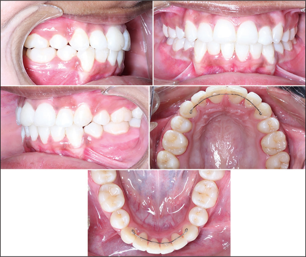
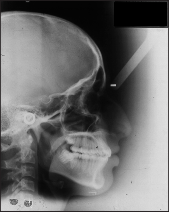
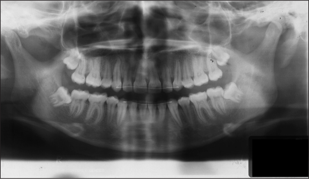
An 18-year-old female patient reported to our department with the chief complaint of irregularly placed upper front teeth. The initial clinical examination revealed the following extra oral features: mesocephalic, mesofacial, mild convex profile with mild posterior divergence and competent lips [Figure 1]. Intraoral examination [Figure 2] revealed Class I molar relation bilaterally, overjet of 1 mm, upper and lower anterior crowding and crossbite in relation to 12 and 43 and in relation to 22 and 33 and instanding 42. Figure 3 is the pretreatment lateral cephalogram and Figure 4 is the pre treatment OPG. Cephalometric findings were orthognathic maxilla and orthognathic mandible with Class I skeletal pattern and ANB of 20. The patient had an average growth pattern. Bolton analysis showed a mandibular anterior excess of 1.2 mm and mandibular overall excess of 2 mm. Arch perimeter analysis revealed 7 mm tooth material excess. Carey’s analysis revealed 7.2 mm tooth material excess. She was diagnosed as an 18-year-old female patient with Class I molar relation superimposed on Class I skeletal bases with ANB of 20, average growth pattern, upper and lower anterior crowding and crossbite in relation to 12 and 43 and in relation to 22 and 33.
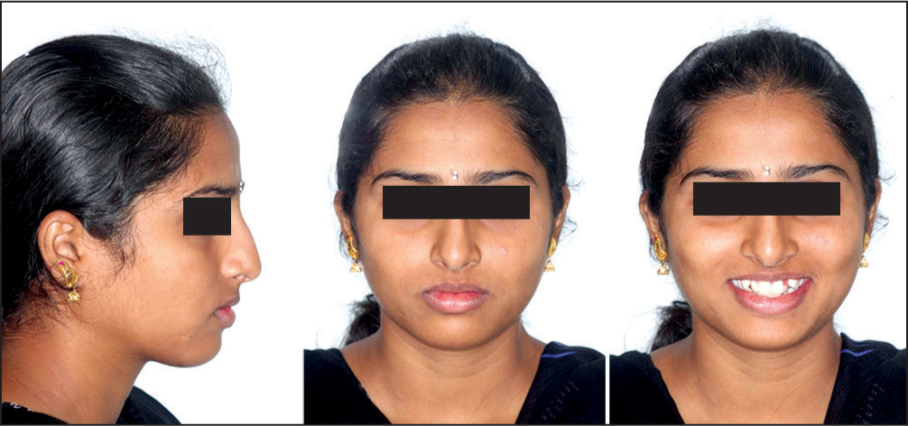
- Pre-treatment extraoral photographs showing mild convex profile and competent lips
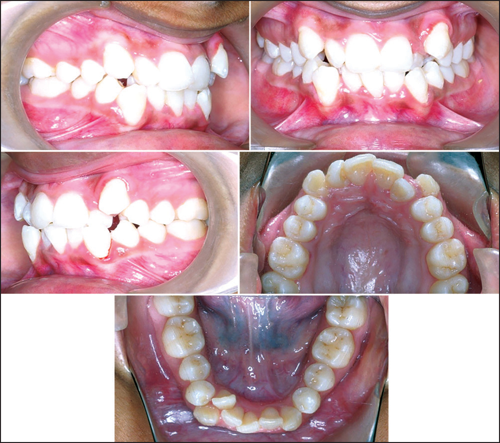
- Pre-treatment intraoral photographs showing Class I molar relation bilaterally, overjet of 1 mm, upper and lower anterior crowding and crossbite in relation to 12 and 43 and in relation to 22 and 33
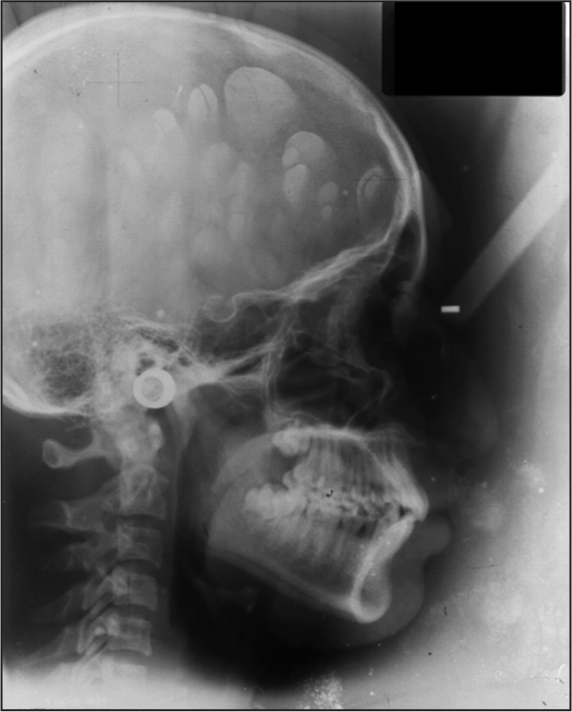
- Pre-treatment lateral cephalogram showing orthognathic maxilla and orthognathic mandible with Class I skeletal pattern and average growth pattern
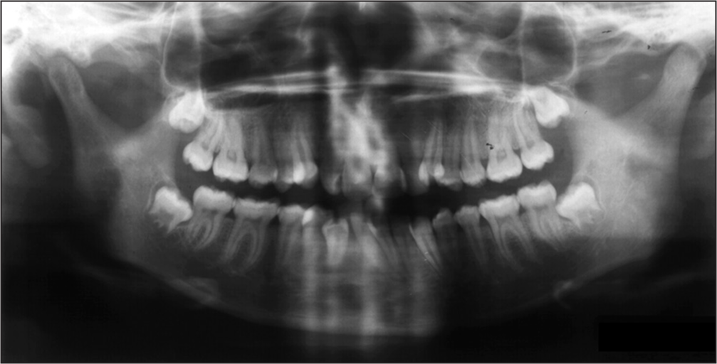
- Pre-treatment orthopantamogram
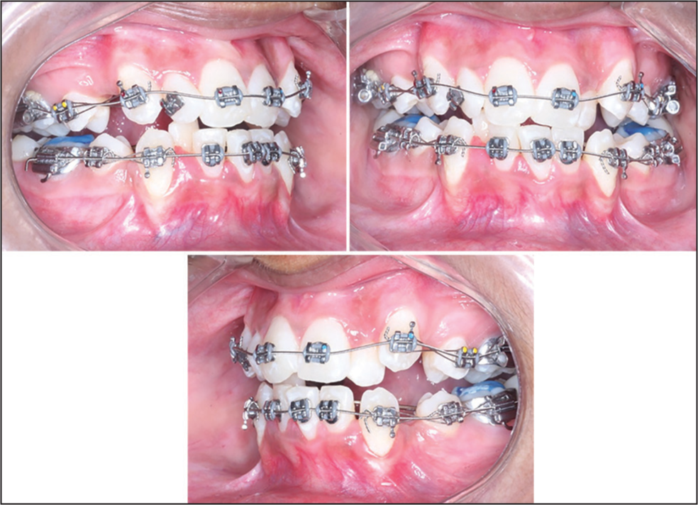
The treatment objectives were to level and align, obtain a pleasing smile and to achieve ideal overjet and overbite. Since the crowding was significant the treatment plan decided was extraction of all 1st premolars to gain the required space in the arch followed by PAE mechanotherapy with 0.022” MBT prescription. Also, for the alignment of 42, and to bring it into the arch by bodily displacement rather than labial tipping it was decided to use a Begg auxiliary (MAA). The anchorage was reinforced using soldered Nance palatal arch in the upper arch and lingual arch in the lower arch [Figure 5]. The sequence of treatment was as follows: in the upper arch we did not bond the brackets initially but waited for driftodontics to bring the canines to a more distal and occlusal position. The lower arch was bonded (except incisors) and tiebacks were used to retract the canines. The initial wire used was 0.0175” coaxial stainless steel [Figure 6]. The occlusion was relieved using light cure glass inomer cement on molars. In 3 months the upper canines had drifted occlusally and distally, the remaining teeth were bonded and tiebacks were continued to retract the canines to gain space for alignment [Figure 7]. Once the remaining lower teeth were aligned and the space for alignment of 42 was created using an open coil spring, the MAA was made using 0.009” Supreme Australian wire* as per the technique by Mollenhauer[5] using Tweed’s pliers and engaged on the lower arch before engaging the main arch wire by tying it to individual brackets [Figure 8]. The inter-box wire segment on either side of 42 was made longer than the other inter-box segments so that it could be deflected lingually to engage 42. The base arch wire during engagement of MAA was 0.016 × 0.022 SS so that there would be no detrimental effects on the arch form and deepening of the bite due to extrusion of the incisors. Once engaged the MAA did not need monthly reactivations. After 3 months another MAA was constructed and used for another 3 months.
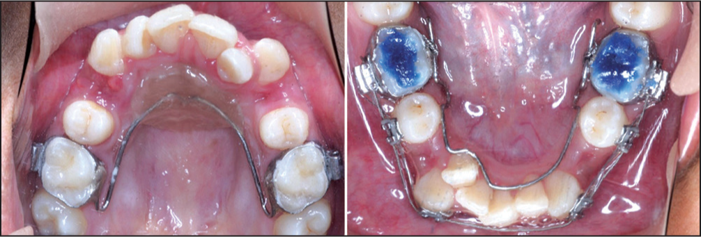
- Anchorage reinforced using soldered Nance palatal arch in the upper arch and lingual arch in the lower arch
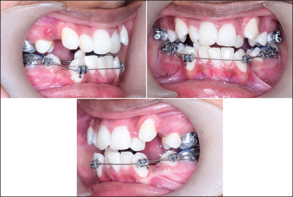
- Initial 0.0175” coaxial wire with lacebacks to retract lower canines
- Upper and lower 0.0175” coaxial wire with active lacebacks
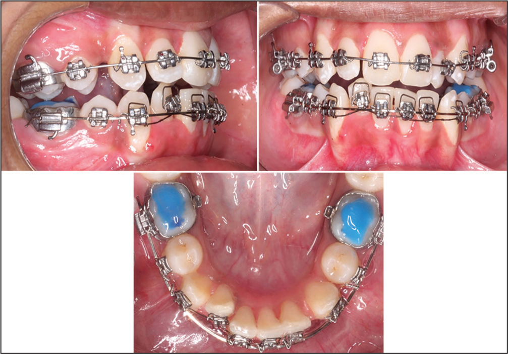
- Upper 0.016” NiTi and lower 0.016” × 0.022” SS with Mollenhauer aligning auxiliary engaged
Use of auxiliaries such as MAA allows for early control over the roots of the teeth without loss of anchorage. The base arch wire of rigid 0.016 × 0.022 SS served to prevent the MAA from torquing the teeth other than 42. In terms of biomechanics, MAA offers certain advantages. The MAA is constructed in a circular shape [Figure 9]. Hence, when the MAA is pulled open and tied to the lower incisor bracket using a ligature wire a couple is generated with the incisal part of the box applying a lingual force on the tooth and gingival part of the box applying a labial force. This couple causes labial root torque with respect to 42 [Figure 10]. Secondly, the height of the box is 3-4 mm long and hence the moment arm for torque delivery using MAA is longer than the moment arm when torque delivery is by rectangular wire in the slot. The longer arm of the MAA is favorable because it will give a higher moment-to-force ratio. This practically means that we can achieve more moment by using a lighter force. It also means that the torque effect of the auxiliary may be active over a larger span of root movement. Hence, the torque expression is more efficient.
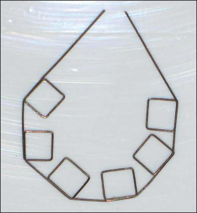
- Design of Mollenhauer aligning auxiliary using 0.009” Supreme Australian wire*
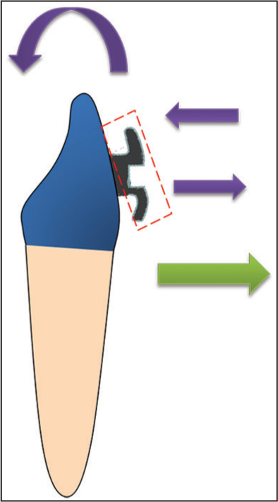
- Biomechanics of action of MAA on lower incisor. Purple arrows indicate the couple force generated and the resultant torque. Green arrow indicates the labial force generated on tying the MAA to the lingually placed tooth
Also, the MAA is made in one plane. The deflection of the MAA in a lingual direction in the region of 42 to engage the tooth will generate a labially directed force which will bring the tooth into the arch. Hence, there is no need of a piggyback Niti wire to bring 42 labially [Figure 10]. The MAA can be similarly used in the upper arch as well but the direction of its engagement should be reversed. In the upper arch, with other techniques such as reversing of brackets, we would have needed to step down the wire. But with use of MAA, as mentioned earlier the advantage is that there is no need to step down to a lower dimension wire since the MAA itself provides the labially directed force.
The 2nd molars were bonded and aligned. Next, on upper 0.019 × 0.025 SS wire with spee and lower 0.017 × 0.025 SS wire with reverse spee, class 2 elastics were used to improve the occlusion [Figure 11].
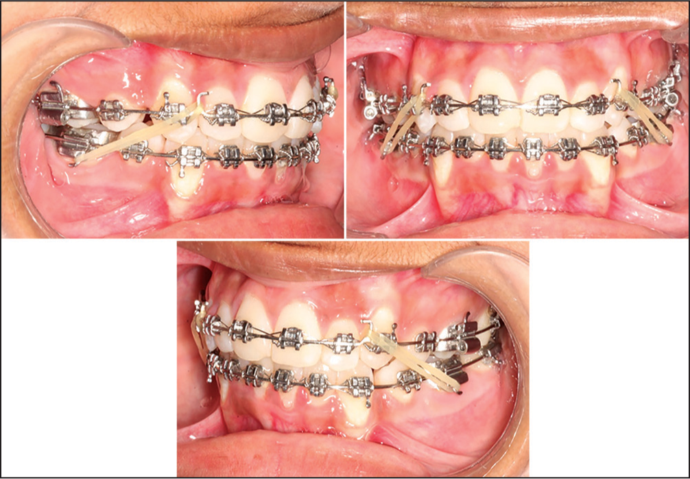
- Second molars bonded, aligned and upper 0.019 × 0.025 SS with spee and lower 0.017 × 0.025 SS with reverse spee with class 2 elastics
CONCLUSION
The post treatment photographs are shown in Figures 12 and 13. The total treatment duration was 26 months. The retention protocol followed was upper Wraparound or Begg retainer with a potential anterior bite plate and upper and lower canine to canine-bonded retainers. The comparison of lower incisor positions before and after treatment is shown in Figure 14 and the improved position of 42 can be seen. No other torque mechanism other than MAA was used and the position of 42 was found to be satisfactory. Post treatment lateral cephalogram and OPG are shown in Figures 15 and 16. The cephalometric comparisons of pre treatment and post treatment are shown in Table 1. There was retroclination seen with respect to upper and lower incisors. There were only minor changes in the incisor positions and inclinations and no change in the skeletal profile. Hence, superimpositions were not considered to be essential as the change in inclination of incisors was negligible.
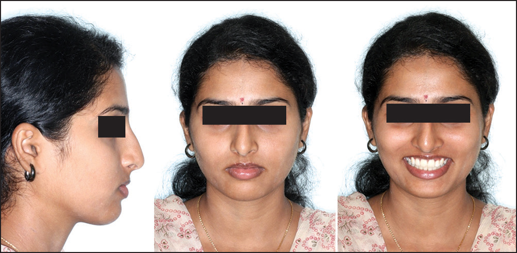
- Post-treatment extraoral photographs
- Post-treatment intraoral photographs
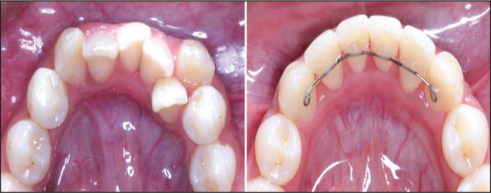
- Comparison of lower incisors before and after treatment
- Post-treatment lateral cephalogram
- Post-treatment orthopantamogram
| Skeletal | Mean | Pre Rx | Present stage | Difference |
|---|---|---|---|---|
| SNA angle | 82° | 82° | 82° | No change |
| SNB angle | 80° | 80° | 80° | No change |
| ANB angle | 2° | 2° | 2° | No change |
| N Perp. — Pt. A (mm) | 0+2 mm | −5 mm | −5 mm | No change |
| N Perp. — Pog (mm) | 0 to -4 mm | −13 mm | −13 mm | No change |
| GoGn — SN (Angle) | 32° | 27° | 27° | No change |
| Angle of inclination | 85° | 85° | 85° | No change |
| LAFH (mm) | 65 mm | 65 mm | No change | |
| Eff. max length | 88 mm | 88 mm | No change | |
| Eff. mand. length | 110 mm | 110 mm | No change | |
| Y- axis angle | 66° | 66° | 66° | No change |
| Facial axis angle | 0° | 0° | 0° | No change |
| Sum of post. angles | 396°+6° | 392° | 392° | No change |
| Dental | ||||
| Ul to NA (Angle) | 22° | 30° | 29° | ↓1° |
| UI to NA (mm) | 4 mm | 5 mm | 4 mm | ↓1 mm |
| Ul to SN (Angle) | 102° | 113° | 112° | ↓1° |
| LI to NB (Angle) | 25° | 29° | 27° | ↓2° |
| LI to NB (mm) | 4 mm | 5 mm | 4 mm | ↓1 mm |
| Li to A-Pog. (mm) | 1-2 mm | 3 mm | 2 mm | ↓1 mm |
| LI — Md. Plane | 90° | 100° | 97° | ↓3° |
| (Angle) | ||||
| Soft tissue | ||||
| S Line — UL (mm) | −2 mm | −2 mm | −2 mm | No change |
| S Line — LL (mm) | 0 mm | −1 mm | −1 mm | No change |
The use of the MAA requires considerable technical skills to correctly shape and activate the auxiliary, hence potentially introducing an operator-dependent source of error.
Hence, in this case we found that the MAA offered several advantages:
Biomechanically more efficient for torque delivery than conventional PAE techniques.
No need to step down the wire since it generates the labial force itself.
In upper arch, use of MAA in cases of instanding incisors eliminates the need to reverse the bracket to get a labial root torque.
Eliminates the need to make individual torque bends in the archwires, use of torque bars etc.
The chairside construction of MAA does require technical skills but the MAA does not require frequent reactivations.
*A.J. Wilcock Pty. Ltd., Whittlesea, Victoria, Australia. Distributed in North America by G&H Wire Company, Franklin, IN; www.ghwire.com.
References
- Improving incisor torque control with nickel titanium Torque Bars. J Clin Orthod. 1999;33:224-30.
- [Google Scholar]
- Assessment of second-order clearances between orthodontic archwires and bracket slots via the critical contact angle for binding. Angle Orthod. 1999;69:71-80.
- [Google Scholar]
- A simple technique for independent torque control with miniscrew anchorage. J Clin Orthod. 2009;43:566-71. quiz 581
- [Google Scholar]
- An aligning auxiliary for ribbon arch brackets: Rectangular boxes from ultrafine high tensile wires. Aust Orthod J. 1990;11:219-26.
- [Google Scholar]