Translate this page into:
A custom made grid to guide placement of temporary anchorage devices
Address for Correspondence: Maj. (Dr.) Raj Kumar Maurya, Dental Officer and Orthodontist Bhopal, Madhya Pradesh, India. E-mail: bracedbyraj@gmail.com
This article was originally published by Wolters Kluwer and was migrated to Scientific Scholar after the change of Publisher.
Abstract
The use of implant anchorage has simplified orthodontic treatment by sparing us the need for patient compliance and the complexity of treatment. One of the most important factors affecting the success of interdental implants is preventing the damage to adjacent roots and periodontal ligament. The most common causes of root damage from mini-implant insertion are improper site selection and an inaccurate angle of drill penetration. We thereby present a custom made modified grid help in more accurate placement of temporary anchorage devices and guide the angle of drill penetration. The grid can be placed anywhere in the oral cavity (buccally, palatally, anteriorly or posteriorly) and it can be attached to the main arch wire, bracket or even on unbounded teeth. The measuring reference grid with two vertical guide arms is connected with a horizontal arm that will later be secured to the adjacent bracket at both ends. The grid includes small squares, which effectively upgrade the efficiency during the orthodontic implant placement. The two vertical guide arms help in maintaining the desired angulation while drilling indicating the mesial and distal root surface of the adjacent teeth.
Keywords
Anchorage
mini-implant
temporary anchorage device
INTRODUCTION
The use of implant anchorage has simplified orthodontic treatment by sparing us the need for patient compliance and the complexity of treatment. Among different type of anchor implants the bone screws seemed to be more popular and widely accepted by orthodontists because, they offer several advantages over the other systems: Smaller fixture, easier surgical procedures, less trauma, lower cost and risk, more clinical indications and more implant sites.[1]
Selecting the proper implant site can be an important factor in the overall success of this treatment approach. Five factors are important in determining an adequate site for implantation:
Indication, system used, and required mechanics.
Placement in attached gingiva.
Sufficient inter-radicular distance.
Avoiding other anatomical structures. E.g., inferior alveolar nerve, artery, vein, mental foramen, maxillary sinus, and nasal cavity.
Adequate cortical bone thickness, to ensure better primary stability and long-term success.[2]
One of the most important factors affecting the success of interdental implants is preventing the damage to adjacent roots and periodontal ligament. During the insertion of the mini-screw, the periodontal ligament is inadvertently invaded; the patient will show symptoms of pain on percussion or mastication. If the root is contacted during insertion, the patient will develop sensitivity to hot and cold.[2]
DIRECTIONS OF IMPLANT INSERTION
The most common causes of root damage from mini-implant insertion are improper site selection and an inaccurate angle of drill penetration. In order to minimize the damage to adjacent structures many authors have advocated that the implant should be inserted at an angulation of 10°-40° to the long axes of the tooth.[3]
Since the placement of inter-radicular implant is of utmost importance for its clinical usage, many authors have devised grid and stents to help accurately locate the ideal site for implant placement.[4-6]
We thereby present a custom made modified grid help in more accurate placement of temporary anchorage devices (TADs) and guide the angle of drill penetration. Authors had used TADs of Abso-anchor (Dentos, Daegu, Korea) in their all cases. The grid can be placed anywhere in the oral cavity (buccally, palatally, anteriorly or posteriorly) and it can be attached to the main arch-wire, bracket or even on un-bonded teeth.
APPLIANCE FABRICATION
The grid consists mainly of three components, (1) screw with nut (2) vertical guide arms and (3) grid [Figure 1].

- Modified grid with two additional vertical arms to guide miniscrew placement
A straight rectangular .017 × 0.025 stainless steel wire is soldered on the head of the G screw. Screw with threads from 40 to 100 threads per inch (0.5 mm to 0.2 mm pitch) made of stainless steel had been used. Same wire will later be secured to the adjacent bracket at both ends. Two vertical guide arms of 15 mm length with hook on one end are secured into the screw with the help of a nut [Figure 2].
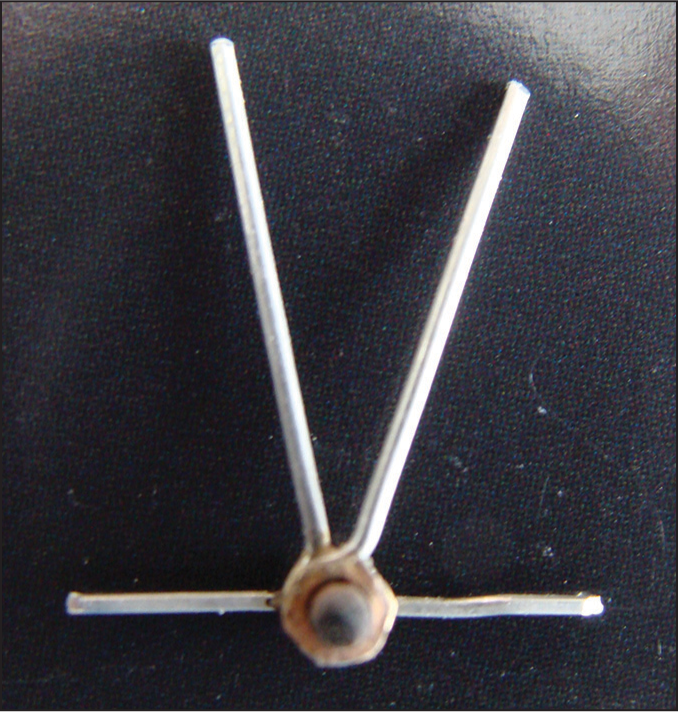
- Verticle guide arms, secured with help of nut
The grid for guiding mini-screw placement is fabricated from straight braided rectangular 0.016″ × 0.022″ stainless steel wire of 9 mm and 5 mm length. Stainless steel ligature wire of 0.012″ is used to construct the squares of the grid such that each small square measures about 1 mm[2] [Figure 3].
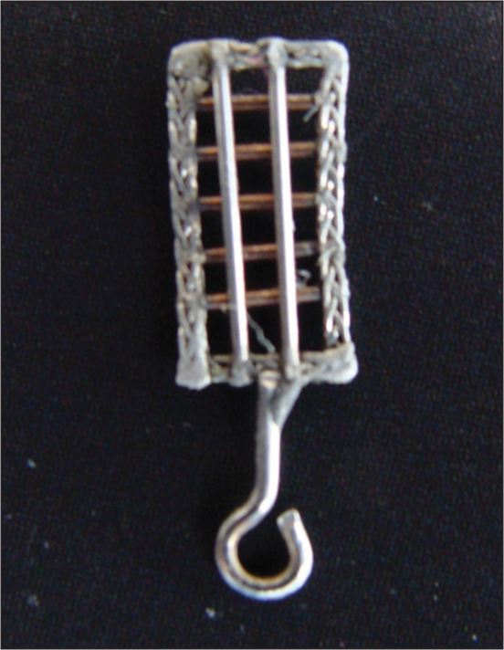
- Grid with a hook soldered on to it
The grid is secured into the screw with vertical guide arms with the help of second nut [Figure 1].
CLINICAL PROCEDURE
When the optimal site and the inclination for each implant have been determined, this information must be conveyed to the insertion stage. The modified grid is placed on the pretreatment ontario power generation (OPG). The vertical guide arms are adjusted on the pretreatment OPG such that it follows the mesial and distal surfaces of the adjacent roots [Figure 4].
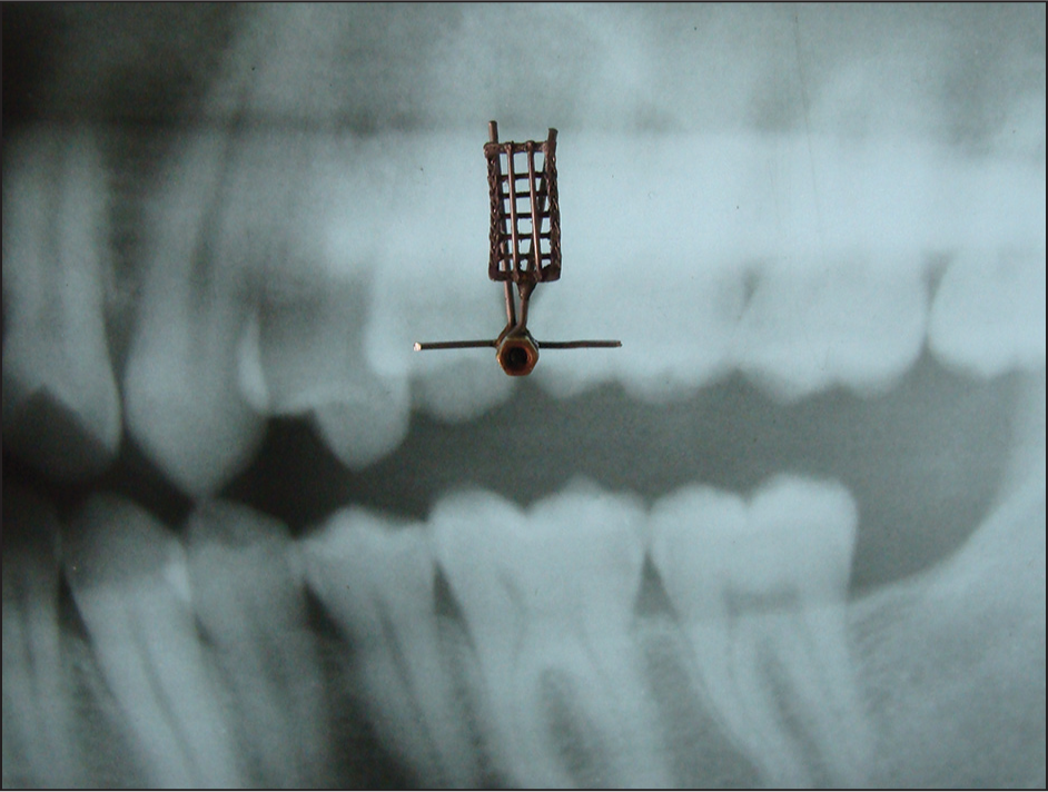
- The vertical guide arms are adjusted on ontario power generation
The grid is now secured to the adjacent brackets, and a peri-apical radiograph is taken with paralleling technique to confirm the angulation of adjacent roots [Figure 5].
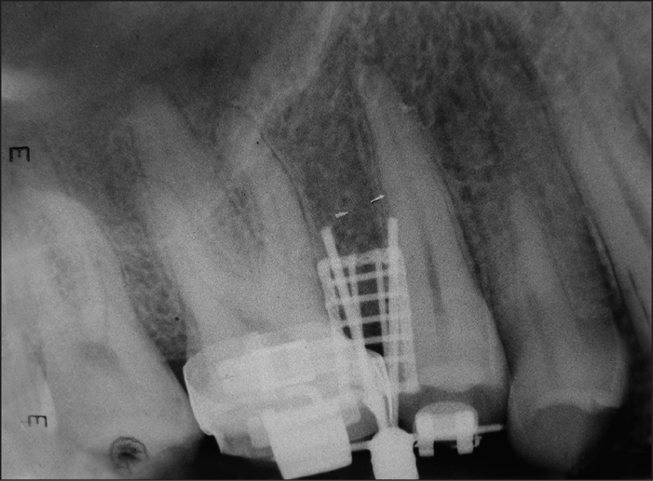
- Intra-oral peri-apical radiograph confirms angulation of roots and point of drill
The appropriate cell of the grid for the exact mini-screw site is selected on the peri-apical radiograph. The site of mini-screw placement is marked with the explorer/scaler [Figure 6].
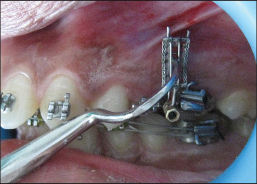
- The site of miniscrew placement is marked with explorer
Now the grid is removed leaving behind the two vertical arms to provide adequate space for pilot drilling [Figure 7]. These vertical arms help in maintaining the desired angulation while drilling, indicating the mesial and distal root surfaces of the adjacent teeth. Placement accuracy is confirmed clinically and radiographically [Figures 8a and b].
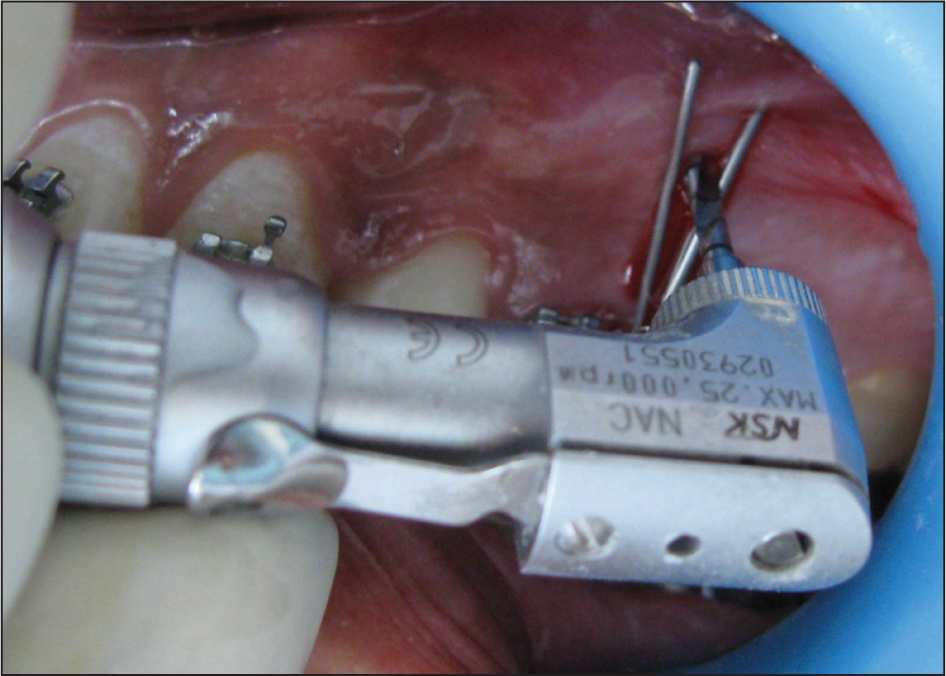
- Vertical arms maintain the desired angulation while drilling
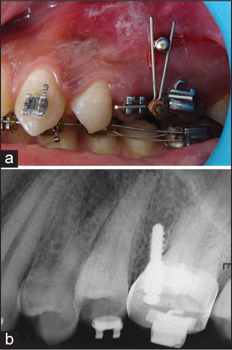
- (a and b) Placement accuracy is confi rmed clinically and radiographically
MODIFICATIONS
For placement of temporary anchorage devices in the mandibular arch
The sulcus depth of the mandibular arch is less than that of the maxillary arch. So the height of the grid should be reduced to place the grid in the mandibular arch. For this purpose, the screw can be inserted in any of the cells of the grid according to the desired height [Figure 9].
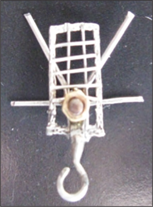
- Screw is inserted into the cell of the grid to reduce the height
For placement of temporary anchorage devices on palatal slope
The grid is fabricated from braided rectangular stainless steel wire so that it can be contoured according to the palatal slope. It can be held in place with the help of a cross over wire from the buccal to the palatal surface [Figure 10].
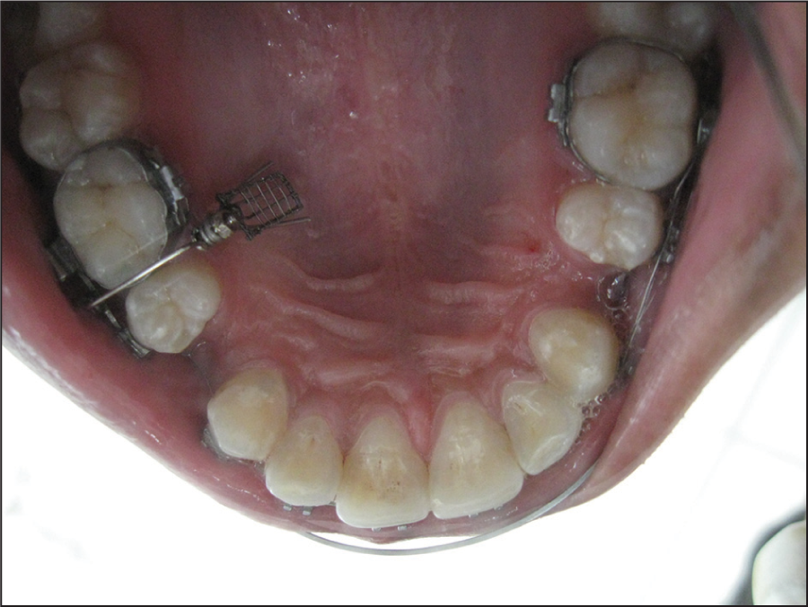
- Grid by cross over wire from buccal to palatal
For placement of temporary anchorage devices before the bracket placement
If the implant placement is required before the placement of brackets, the grid can be held in place with the help of acrylic (light cure/self-cure) template [Figure 11].
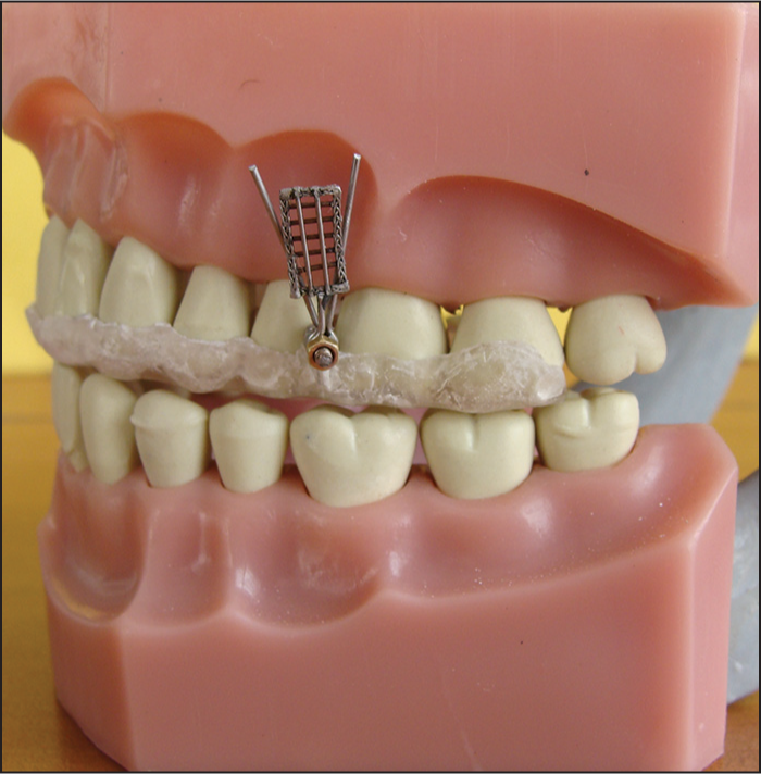
- The grid is held in place with the help of acrylic template
Retractable grid
With this type of modification, once the site of mini-screw placement is located, the removal of grid is not required. The grid can be retracted at 180° angulation leaving behind the two vertical guide arms [Figure 12].
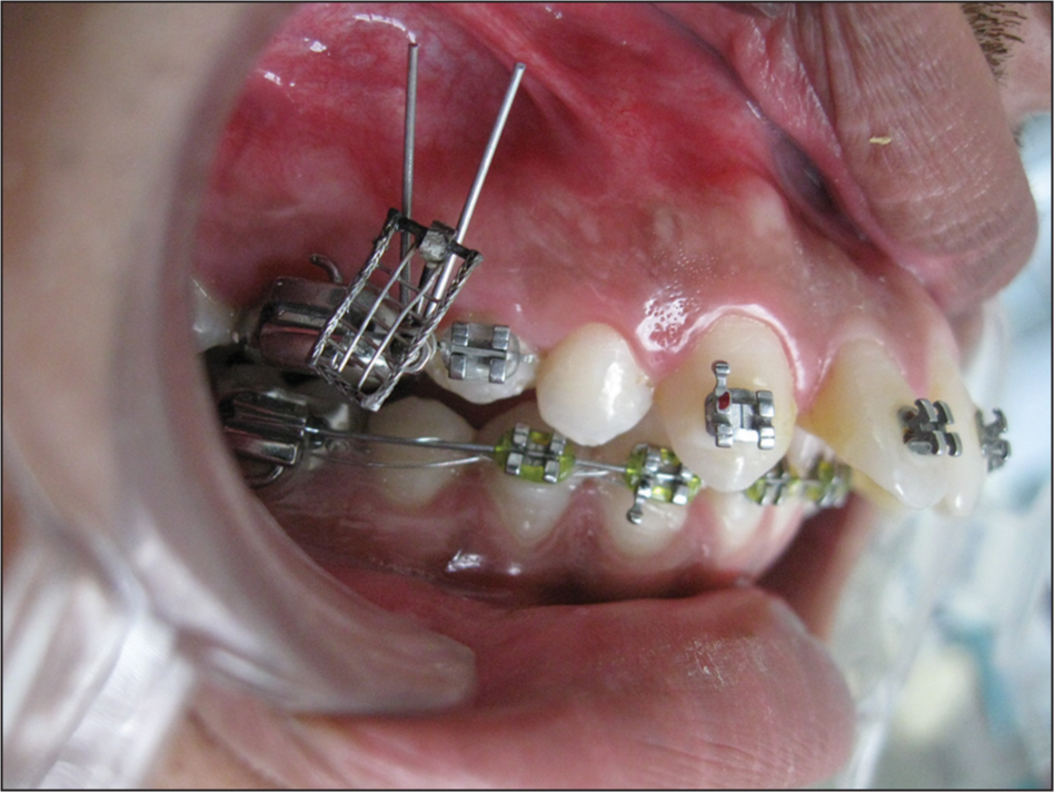
- The grid can be retracted at 180° angulation
Grid with Guerin type lock
Alternatively, the grid can be attached to a locking device that is Guerin type lock made from an electrical connector with a screw at both ends. A slot is cut edgewise into the metal block of the locking device so that appliance can be seated directly onto the arch wire [Figure 13].
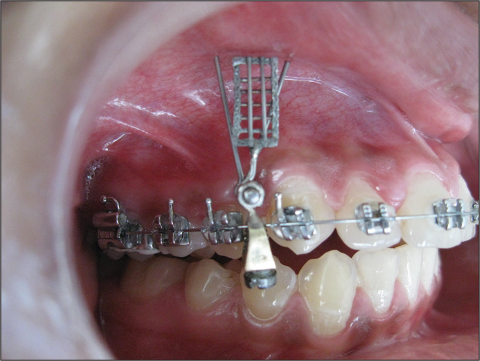
- The grid is secured on to main arch wire Guerin lock
CONCLUSION
Though the use of the custom made modifi ed grid, the implant can be precisely and dependably placed in areas of reduced space approximating important anatomical structures. The versatility of the grid lies in the fact that it can be modified to suit different anatomic location and clinical situations.
References
- Mini-implant anchorage for the orthodontic practitioner. Am J Orthod Dentofacial Orthop. 2008;133:621-7.
- [Google Scholar]
- Miniscrew anchorage used to protract lower second molars into first molar extraction sites. J Clin Orthod. 2003;37:575-9.
- [Google Scholar]
- The use of temporary anchorage devices for molar intrusion. J Am Dent Assoc. 2007;138:56-64.
- [Google Scholar]


