Translate this page into:
A simple system for improving the accuracy of IZC bone screw placement

*Corresponding author: Sumedh Deshpande, Department of Orthodontics and Dentofacial Orthopaedics, KLE Vishwanath Katti Institute of Dental Sciences, KLE Academy of Higher Education and Research, Belagavi -590 010, Karnataka, India. deshpandesumedh93@gmail.com
-
Received: ,
Accepted: ,
How to cite this article: Deshpande S, Shenoi SB, Hattarki R. A simple system for improving the accuracy of IZC bone screw placement. APOS Trends Orthod 2020;10(4):259-61.
Abstract
An operator often finds it hard to assess the ideal timing to start angulating the driver while placing infrazygomatic crest screws. Thus, we have designed a simple system to guide the operator to know exactly when the angulation of the driver should be started for the ideal placement of the IZC screw. The components of the system include the calculation of the amount of tissue that needs to be pierced perpendicularly and the fabrication of an indicator device over the implant driver with a stainless steel wire. Hence, using this system, the proper timing for angulation can be obtained, thus improving the accuracy of placement.
Keywords
Infrazygomatic crest screw
Temporary anchorage device
Angulation
Skeletal anchorage
Biomechanics

Infrazygomatic crest screws are usually placed at the IZC 6 OR IZC 7 regions, with a 55–70 angulation.[1]
The operator is expected to start angulating the implant driver once the cancellous bone is just reached, after a perpendicular insertion through the cortical bone and gingiva.[1]
Failure of angulation at the right time can lead to:
Inaccurate ideal final angulation, leading to trauma to the buccal mucosa
Inter radicular placement of the screw.
Asymmetrically placed IZC screws on the left and right side of the mouth can lead to alteration of biomechanics.
An operator often finds it hard to assess the ideal timing to start angulating the driver while placing the implant.
Thus, we have designed a system to guide the operator to know exactly when the angulation of the driver should be started for the ideal placement of the IZC screw.
COMPONENTS OF THE SYSTEM
Calculation of the amount of tissue that needs to be pierced perpendicularly
Fabrication of an indicator device.
Steps in calculating the amount of tissue that needs to be pierced perpendicularly
Measurement of soft-tissue (X mm) covering the insertion site using the stopper method with an endodontic file [Figure 1]
Measuring the cortical bone thickness (Y mm) with a pre-existing CBCT, or using the average cortical bone thickness values (1.44 ± 0.39 in adolescents, 1.58 ± 0.34 in adults) as given by Farnsworth et al.[2]

- Measurement of soft-tissue thickness.
Thus X + Y= Z, Where Z mm is the total thickness of the soft tissue, along with the cortical bone thickness at the insertion site.
Steps in the fabrication of the indicator device
Wind 2–3 helices around the implant driver attachment with a 0.7 mm stainless steel wire such that the distal-most helix approximates with the projection on the head of the implant driver attachment. This will be taken as the standard reference point, point S [Figure 2].
Approximately 1.5 mm away from the driver attachment, bend the wire at point 1 such that it runs parallel to the driver [Figure 2]
Point 2 should approximate the tip of the bone screw [Figure 2]
From point 2, incorporate a helix in the wire such that it acts as a soft tissue stopper [Figure 2].
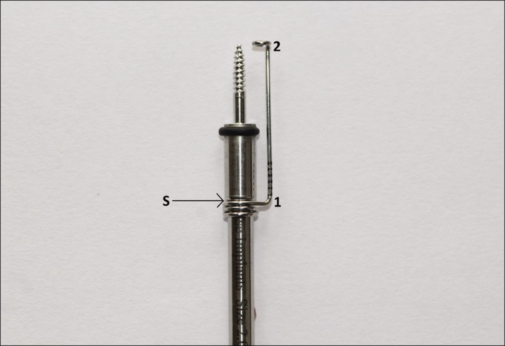
- Indicator device made with 0.7 mm SS wire on the implant driver attachment.
Millimetric markings are transferred onto the indicator device, as shown in Figure 2.
With point S as a reference, the indicator device is adjusted according to the Z value obtained, by coinciding the millimetric marking with point S.
For example, if,
X = 2 mm and Y = 2 mm, Z = 4 mm, which is adjusted on the scale [Figure 3].
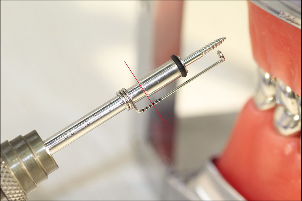
- Indicator device adjusted to 4 mm.
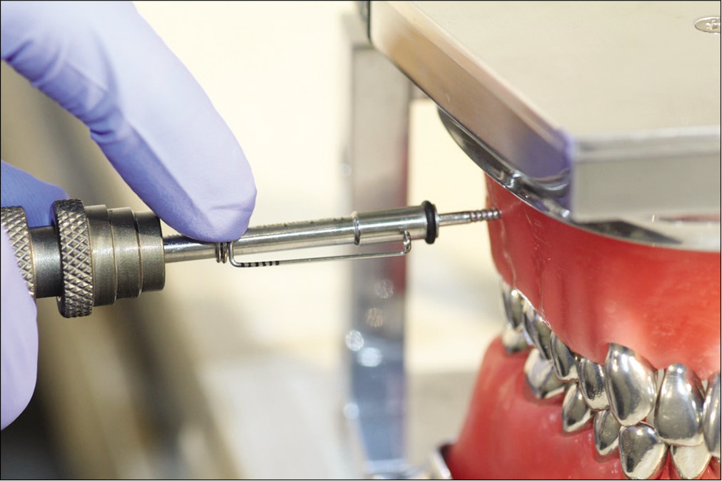
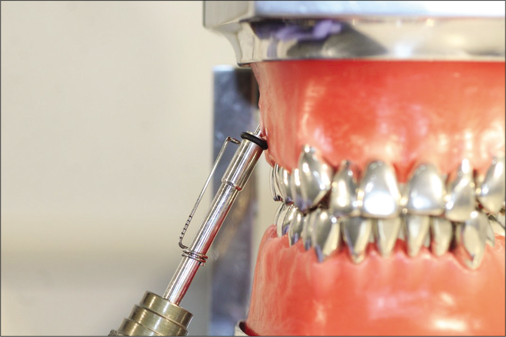
The bone screw is now inserted perpendicularly through the soft tissue and cortical bone [Figure 4] until the helical stop on the indicator device touches the soft tissue [Figure 5].
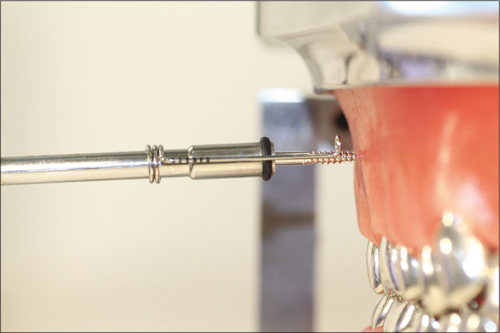
- Perpendicular insertion.
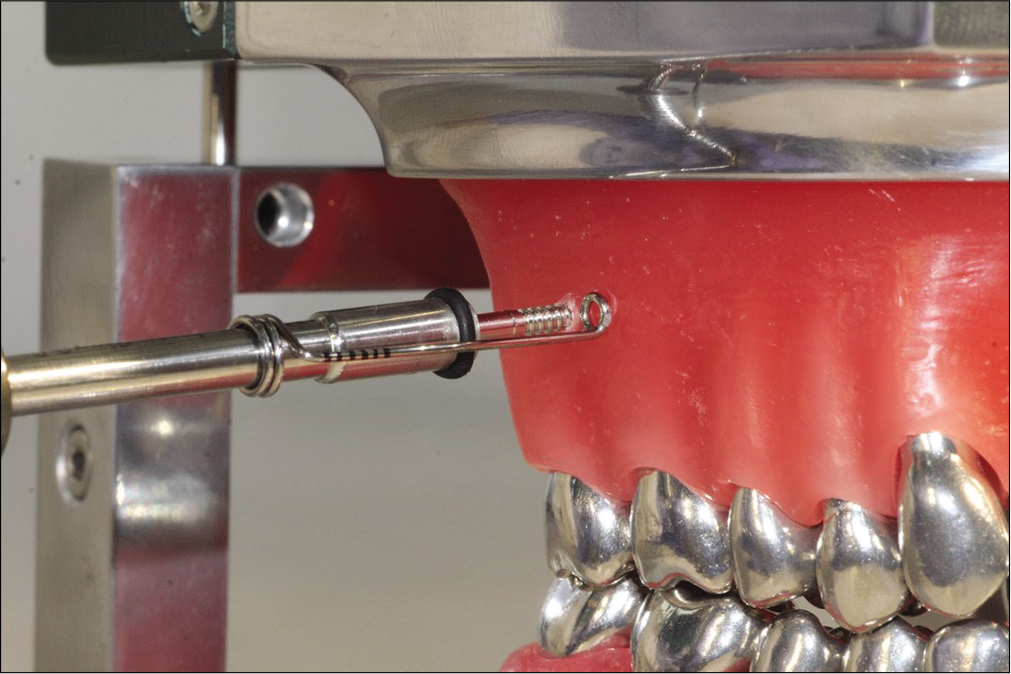
- Gingiva and cortical bone pierced as indicated by the helix touching the soft tissue.
Once the stop touches the tissue, the indicator device is slid down on the driver attachment [Figure 6], and from this point, angulation of the driver is advised until the insertion is complete [Figure 7].
- Indicator device slid down on the implant driver attachment.
- IZC screw completed inserted at the desired angulation.
Hence, using the system, the proper timing for angulation can be obtained, thus improving the accuracy of placement [Figure 8].
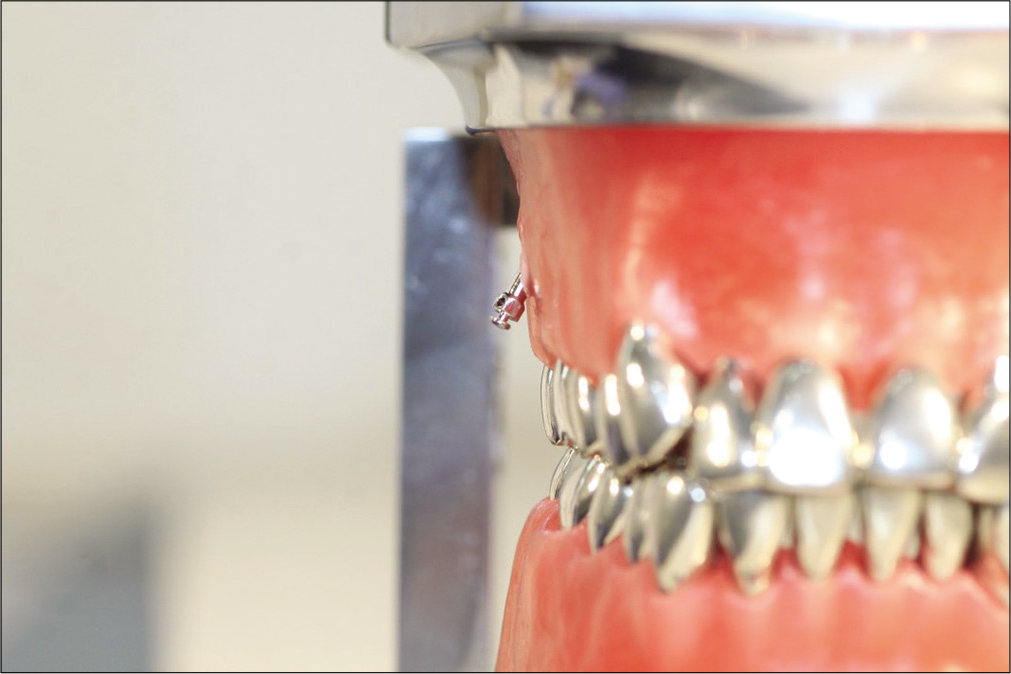
- Accurate final IZC screw placement.
Declaration of patient consent
Patient’s consent not required as there are no patients in this study.
Financial support and sponsorship
Nil.
Conflicts of interest
There are no conflicts of interest.
References
- CBCT Imaging to diagnose and correct the failure of maxillary arch retraction with IZC screw anchorage. IJOI. 2014;3:4-17.
- [Google Scholar]
- Cortical bone thickness at common miniscrew implant placement sites. Am J Orthod Dentofac Orthop. 2011;139:495-503.
- [CrossRef] [PubMed] [Google Scholar]