Translate this page into:
The accuracy of computer-aided design and manufacturing surgical-guide for infrazygomatic crest miniscrew placement

*Corresponding author: Prajak Jariyapongpaiboon, Dental Department, Rajavithi Hospital, Bangkok, Thailand. prajakjariya@gmail.com
-
Received: ,
Accepted: ,
How to cite this article: Jariyapongpaiboon P, Chartpitak J, Jitsaard J. The accuracy of computer-aided design and manufacturing surgical-guide for infrazygomatic crest miniscrew placement. APOS Trends Orthod 2021;11(1):48-55.
Abstract
Objectives:
Infrazygomatic crest (IZC) surgical guides have been employed to prevent any avoidable complications during miniscrew insertion. The purpose of this study was to evaluate the accuracy of IZC miniscrew placement when using a surgical-guide developed by computer-aided design and manufacturing (CAD/CAM) techniques.
Materials and Methods:
Ten patients were scanned with cone-beam computed tomography for three-dimensional (3D) planning of IZC miniscrew placements. The upper arches were scanned separately, and virtual miniscrews were placed in the position planned by 3D software. The CAD/CAM surgical guides were designed and fabricated individually to enable accurate miniscrew placement. Subsequently, 20 self-drilling miniscrews were inserted at the right and left IZC areas using 5 CAD/CAM surgical guides (CS group, n = 10) and direct insertion (DI group, n = 10), respectively. Pre- and post-operative digital model images were compared, actual and planned miniscrew positions were superimposed and measured for 3D angular and distance deviations in the two groups. Comparisons between groups were made using the Kruskal–Wallis test.
Results:
In the CS group, the median coronal and sagittal angular deviations were 2.95 degrees (range 0.34–5.26 degrees) and 2.05 degrees (range 0.38–4.08 degrees), respectively, while the median coronal and apical deviations were 0.39 mm (range 0.24–0.51 mm) and 0.50 mm (range 0.16–0.66 mm). These deviations differed significantly from those of the DI group.
Conclusion:
The IZC CAD/CAM surgical guide has made it possible to control miniscrew placement with high precision.
Keywords
Orthodontic miniscrews
Infrazygomatic crest
Computer-aided design and manufacturing surgical guide
Metal sleeve-free surgical guide
Accuracy

INTRODUCTION
In recent years, the use of orthodontic miniscrews for absolute anchorage has begun to offer wider treatment capabilities as well as increased efficiency.[1,2] Its use has also led to more favorable outcomes in the treatment of many cases such as posterior maxillary teeth intrusion, mesial tooth movement for closure of extraction space, or maxillary whole arch distalization.[2,3] Orthodontic miniscrews have great mechanical retention together with several other advantages, including having sufficient anchorage in non-compliant patients, being minimally-invasive, allowing simplicity of insertion and removal, and being relatively cheap.
The infrazygomatic crest (IZC) is a placement site in the maxilla suitable for orthodontic miniscrews. A bony ridge running along the curvature between the alveolar and zygomatic processes, it is located above the maxillary first molar in adults.[4] It has been used successfully to provide skeletal anchorage,[5-7] and it is advocated for extra-alveolar miniscrew insertion to allow more versatility of orthodontic movement, since tooth roots do not interfere in tooth displacement. IZC screw is more reliable for maxillary retraction than high IZC or routine inter-radicular space;[8] moreover, high success rates of 79.2–93.7 % have been reported.[9,10]
Liou et al.[4] suggested orienting screws at 14–16 mm above the maxillary occlusal plane and maxillary first molar with an angle of insertion of between 55 and 70 degrees to the maxillary occlusal plane to achieve maximal buccal bone engagement. The amount of buccal alveolar bone to the first maxillary molars should be taken into account when planning miniscrew placement. In some cases, buccal bone thickness is scant, and in this scenario, accurate positioning is crucial. Lin and Roberts have reported that the alveolar bone is thicker on the buccal surface of the second maxillary molar, so IZC placement buccally to the second maxillary molar is usually preferable for miniscrew positioning.[11]
A common problem is that IZC miniscrew insertion may injure the structure around the insertion area due to lack of precise knowledge of the patient’s anatomy; consequently, injury to the mesiobuccal root of the maxillary first molar and low stability caused by root contact are risks encountered during miniscrew placement. Direct insertion (DI) without accurate surgical guidance has been found to result in a 20% injury rate during screw positioning.[12] Several methods of miniscrew implantation aimed at enhancing the precision of the insertion of the screws and minimizing root contact have been described in the literature. The technique of inserting radiopaque markers, such as brass stainless-steel wires or metal tubes, into the interproximal space of the implant site has recently been adopted.[13,14] Another method, in which the miniscrews are placed using a resin splint-type guide made from a plaster model, has also been introduced.[15]
To optimize miniscrew placement and to reduce surgical complications, the clinician must have full knowledge of the patient’s oral bone anatomy so that any osseous topography and bone volume conditions can be taken into account during planning. Two-dimensional (2D) radiographic imaging-based guides can only transfer 2D information to the three-dimensional (3D) region, which is not sufficient to eliminate the risk of root damage and improve stability.[16]
Cone-beam computed tomography (CBCT) is used to evaluate 3D structures in the dentofacial area, entailing reduced radiation doses, and lower costs compared with medical CT; furthermore, it obtains finer images. Miyazawa et al.[15] showed that 52.3% of cases required a change of location or angle after surgery, as evaluated by CBCT.
Methods for fabrication of surgical guides using 3D imaging techniques including CBCT, 3D software, and 3D printers, have been reported to reduce angular and distance deviation during drilling and insertion, especially in patients with difficult anatomical problems, and these methods improve the stability and success rates of miniscrews.[17,18] CBCT images are, therefore, taken for evaluation of alveolar bone conditions. The use of 3D programs enables accurate positioning and design of surgical guides for miniscrew implantations, and these guides are produced with a 3D printer.
In the field of dental implantation, the method of placement has recently shifted from DI assessed by the surgeon to placement of implants by means of computer-guided surgical systems, with nearly exact predictability of the final surgical outcome.[16] Likewise, an orthodontic application for miniscrew surgical guides has been developed for inter-radicular[17] and palatal miniscrew placement.[18] IZC surgical guides need to result in enhanced accuracy; therefore, the purpose of this study was to evaluate the accuracy of IZC miniscrew placement when using the DI and computer-aided design and manufacturing (CAD/ CAM) surgical guide methods.
MATERIALS AND METHODS
The study protocol was reviewed and approved by the ethics committee of Rajavithi Hospital (#031/2018), Department of Medical Services, Ministry of Public Health, Bangkok, Thailand.
Ten patients, one male and nine females, of mean age 27.8 (minimum 20.7 and maximum 45.5 years old) who needed orthodontic therapy were included in this study. The treatment plan required skeletal anchorage for anterior retraction or maxillary whole arch distalization. The patients were evenly allocated at random to DI and CAD/CAM surgical guide (CS) groups.
The miniscrews (PW Plus CO., LTD, Nakornprotom, Thailand) used in this study were a taper-type, 1.8 mm in diameter and 9.8 mm in length, and the body had a thread length of 6 mm. For 3D study, the standard tessellation language (STL) file of the miniscrew was exported as “virtual miniscrew.” The miniscrew driver, used for connecting the miniscrews, had a cylindrical shape at the tip which was 4.0 mm in diameter and 4.0 mm in height.
The position of IZC miniscrews
The upper arches were scanned with CBCT using a Dentri (HDXwill Co., Ltd, Seoul, Korea) with 80 kV, 10 mA, FOV 16 cm (diameter) × 14.5 cm (height), and voxel size 0.2 mm. The digital imaging and communications in medicine files from the CBCT were imported with 3D software (OnDemand3D; Cybermed, Seoul, Korea). The position for each miniscrew was determined for safe and optimal miniscrew placement, and the relationship between the root and buccal bone was evaluated in coronal and sagittal views [Figure 1a]. The position of the miniscrews was a midline between the lamina dura of the mesial root of the second molars and the buccal bone surface in coronal view, and the area where this direction met the outer cortex indicated the insertion point. In sagittal view, the insertion point and direction were at the inter-radicular space between the distal root of the first molar and the mesial root of the second. The insertion depth of the planned miniscrews was 6 mm, as the whole body of the miniscrew was completely embedded in the alveolar bone. The direction and position of the miniscrew heads and tips were recorded as the “planned position.”
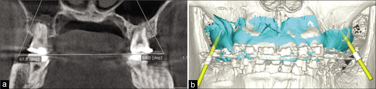
- Infrazygomatic crest miniscrew position was planned using cone-beam computed tomography (a) which was fused with digital model images (blue) before the driver key (yellow rods) was located (b).
The upper arches were scanned using an intra-oral scanner (IOS) (Straumann® Virtuo Vivo™, Dentalwings Inc., Montreal, Canada) and exported as STL files. Virtual miniscrews were placed in pre-operative digital models that matched the planned position using Geomagic Studio software (3D System Inc., South Carolina, USA) and were saved as “planned miniscrew.”
Fabrication of CAD/CAM surgical guide
The STL file of the upper arch was fused with CBCT image using designated implant planning software (coDiagnostiX, Dental Wings GmbH, Duesseldorfer, Germany). After segmentation of the CBCT data and matching with the STL file, the planned position of the miniscrews was made for the direction and insertion depth both for the coronal and sagittal plane [Figure 1b]. The miniscrew driver key, which guides the driver head to the desired direction and depth, was then created from the 3D direction of the planned miniscrew. This driver key was metal sleeve-free. The miniscrew driver key width was 4.05 mm in diameter and 6 mm in height to fit the miniscrew driver head and control the direction [Figure 2]. The distance from the upper part of the miniscrew driver key was 7 mm to the bone surface. This method controls the position and direction of miniscrew insertion from the beginning until the miniscrews are inserted into the planned position. The surgical guides were designed in a tooth-borne shape and bilaterally, and each guide included six teeth, right and left upper second premolars, and first and second molars with two connection bars to ensure stability. All parts of the surgical guide were designed with 3 mm thickness for strength.
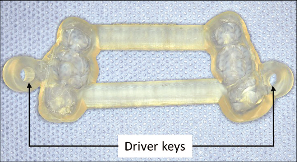
- Computer-aided design and manufacturing surgical guide with two driver keys.
A corresponding tooth-supported stereolithographic surgical guide was printed by a 3D printer (Bego Varseo S, Bremer Goldschlägerei Wilh. Herbst GmbH and Co., Bremen, Germany). To avoid bacterial contamination, the surgical guide was submerged in 1% chlorhexidine for 12 h before miniscrew placement
Surgical procedures
Patients were instructed to rinse with a 0.12% chlorhexidine solution for 30 s. Surgical insertion of miniscrews was performed in accordance with the treatment plan that had been allocated. All surgery was performed by the same experienced clinician (JP).
DI method
After local anesthesia, miniscrews in the DI group were inserted using operator sense and visibility manipulation using the “planned position” as a reference. The operator located the insertion point using a dental probe to measure both mesiodistal and vertical distance from the mesiobuccal cusp of the second molar. The miniscrews were inserted directly into the bone with a manual screwdriver. They were placed upright to the bone surface and then turned slowly for three to four rounds with light pressure until the tip of the miniscrew penetrated the cortex bone. The screwdriver was tipped until the angle of insertion was the same as that of the planned position. The screwdriver was then turned until the entire miniscrew body was embedded into the alveolar bone at the planned depth [Figure 3a].
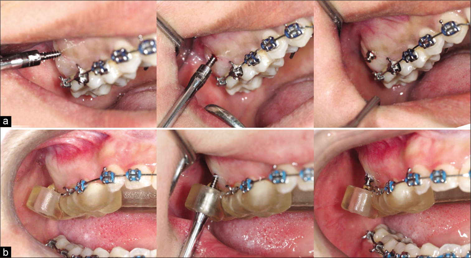
- Miniscrew insertion method direct insertion (a) and CAD/CAM surgical guide (b) groups.
CAD/CAM surgical-guided procedure
For the CS group, the CAD/CAM surgical guides were designed and fabricated individually to facilitate accurate miniscrew placement. The guide was fixed in the upper arch by patient bite force. After the miniscrew was connected to the screwdriver head, it was inserted into the driver key until the tip of the miniscrew touched the bone surface. The screwdriver head was totally covered by the driver key and firmly fitted; thus, the driver key was able to fully control the driver head in 3D. The operator turned the driver slowly until the body of the miniscrew was embedded in the alveolar bone as indicated by a marker on the driver tip [Figure 3b]. All patients were instructed to clean the miniscrew with a tooth brush after meals. In addition, they were advised to use a 0.12% chlorhexidine solution to rinse twice daily for 7 days.
Accuracy analysis
After miniscrew insertion, the miniscrew heads were brushed with a thin layer of titanium dioxide free pigment suspension (Vita powder scan spray, Lorsch, Germany) to enhance the quality of the scanned images. The upper arch was scanned with the same IOS and exported to post-operative digital models. The heads of the scanned miniscrews were split off and superimposed with the reference to the heads of the virtual miniscrews using the best fit alignment function. The new position of the virtual miniscrew was saved as “actual miniscrews.” Finally, the actual miniscrew positions were located in post-operative digital models. These superimposed miniscrews were saved as “actual miniscrews” [Figure 4].
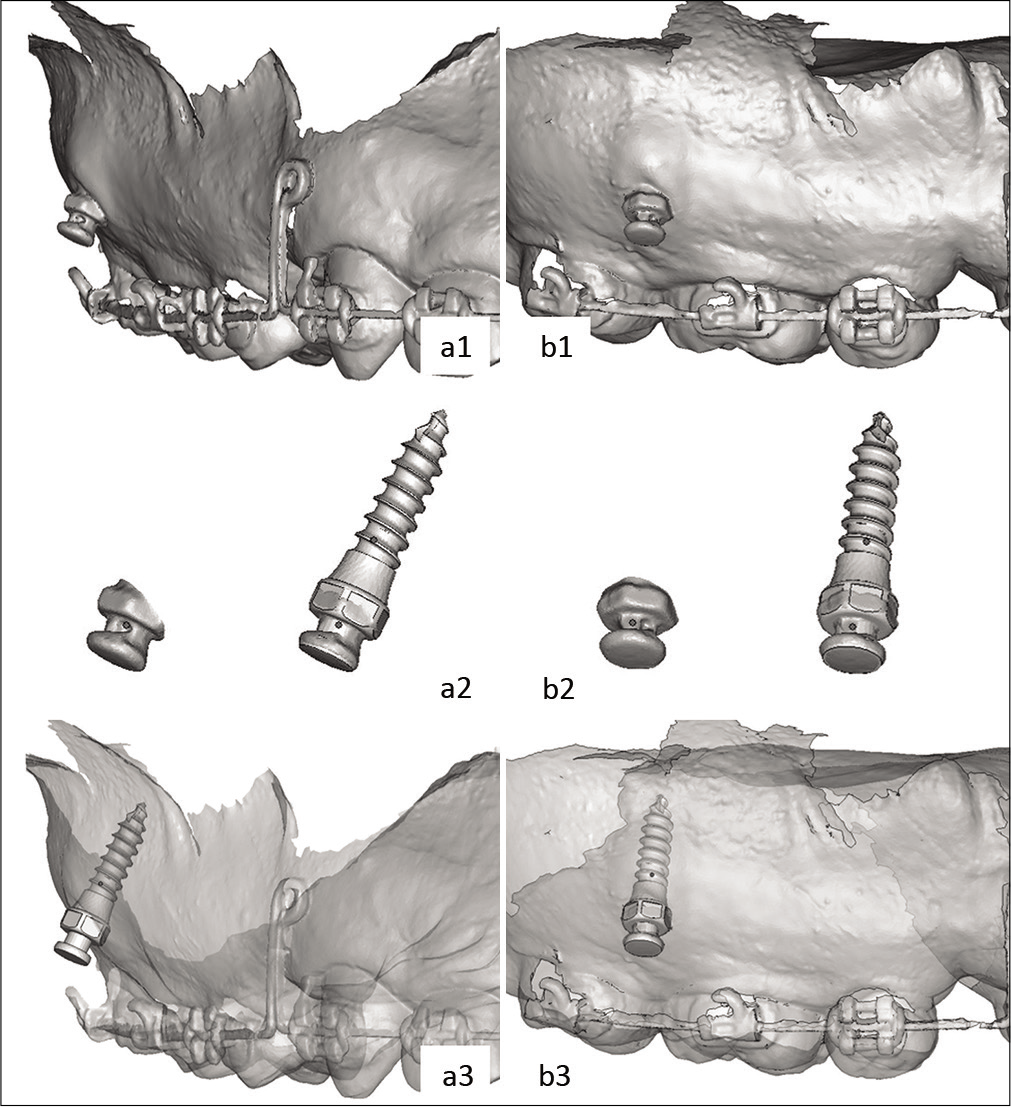
- Coronal (a1) and sagittal (b1) view of post-operative digital models. The heads of the scanned miniscrews were split off and superimposed with the heads of the virtual miniscrews (a2, b2). The actual miniscrew positions were located in post-operative digital models (a3, b3).
Pre- and post-operative digital models were superimposed and compared using the best fit alignment function. Actual and planned miniscrew positions were measured as 3D angular and distance deviation for the coronal and sagittal planes between groups [Figure 5]. The superimposition and deviation measurements were all performed with Geomagic Studio software. The deviations were further calculated and resulted in the following parameters [Table 1]:
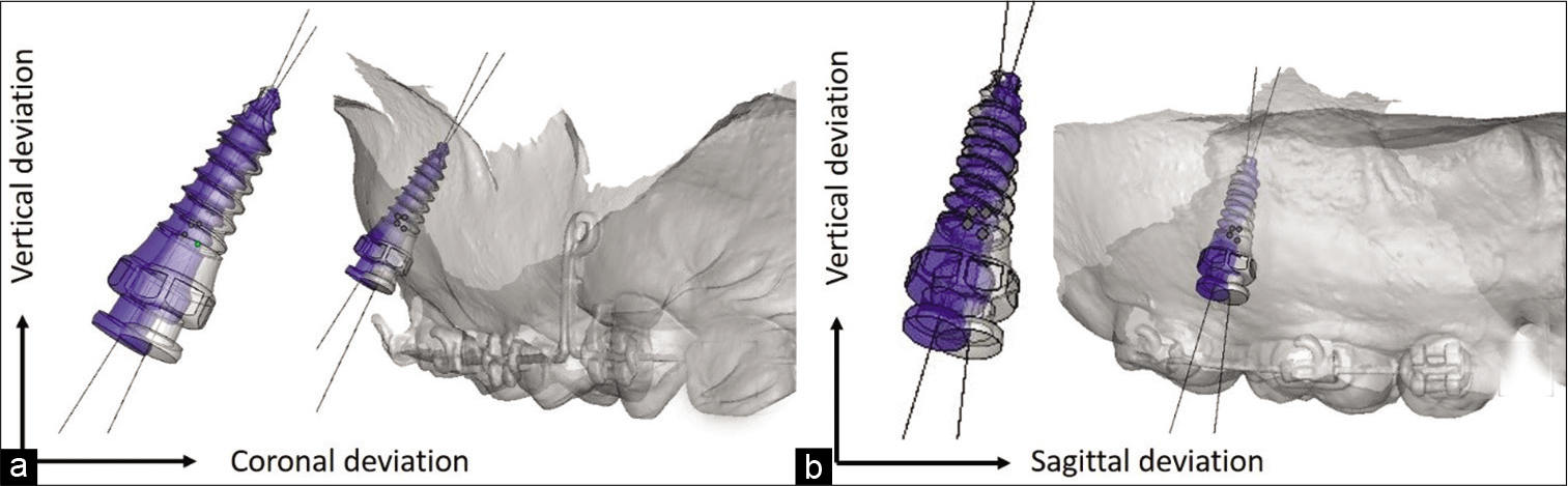
- Actual (gray) and planned (blue) miniscrew positions were measured as 3-dimension angular and distance deviation in coronal (a) and sagittal (b) plane.
| No. | Parameters | Abbreviation | Unit |
|---|---|---|---|
| 1. | Coronal angular deviation | CAD* | Degrees |
| 2. | Sagittal angular deviation | SAD* | Degrees |
| 3. | Coronal overall deviation | COD* | mm. |
| 4. | Coronal lateral deviation | CLD | mm. |
| 5. | Coronal mesiodistal deviation | CMD | mm. |
| 6. | Coronal vertical deviation | CVD | mm. |
| 7. | Apical overall deviation | AOD* | mm. |
| 8. | Apical lateral deviation | ALD | mm. |
| 9. | Apical mesiodistal deviation | AMD | mm. |
| 10. | Apical vertical deviation | AVD | mm. |
As the major complication was root injury, angular and miniscrew distance deviation at apical positions CAD, SAD, COD, and AOD was considered the primary outcome of the study. The other parameters were considered secondary outcomes for testing the accuracy of the two methods.
Statistical analysis
The comparisons between groups were evaluated using Mann–Whitney U-test for significant differences between treatment groups in terms of primary and secondary deviation, adjusting for possible correlation within subjects.
RESULTS
The analyses of the parameters of each treatment group are shown in [Table 2]. With regard to the primary outcome of the study, in the CS group, the median coronal and sagittal angular deviations were 2.95 degrees (range 0.34– 5.26 degrees) and 2.05 degrees (range 0.38–4.08 degrees), respectively, while the median coronal and apical deviations were 0.39 mm (range 0.24–0.51 mm) and 0.50 mm (range 0.16–0.66 mm). These deviations differed significantly from those of the DI group, and all secondary outcomes of the CS group were significantly more accurate than those of the DI group. The results for CAD, SAD, AOD, and COD are illustrated by means of box plots [Figure 6].
| Parameters | DI | CS | P-value | ||
|---|---|---|---|---|---|
| Median | Min-Max | Median | Min-Max | ||
| CAD | 16.03 | 5.68–27.35 | 2.95 | 0.34–5.62 | 0.0002 |
| SAD | 8.9 | 1.04–17.58 | 2.05 | 0.38–4.08 | 0.0032 |
| COD | 1.82 | 1.31–3.01 | 0.39 | 0.24–0.51 | 0.0002 |
| CLD | 0.88 | 0.47–1.74 | 0.23 | 0.04–0.42 | 0.0002 |
| CMD | 0.58 | 0.10–1.87 | 0.24 | 0.01–0.33 | 0.0004 |
| CVD | 1.31 | 0.18–1.88 | 0.12 | 0.00–0.34 | 0.0082 |
| AOD | 1.89 | 1.23–2.97 | 0.5 | 0.16–0.66 | 0.0002 |
| ALD | 1.31 | 0.72–1.70 | 0.28 | 0.13–0.42 | 0.0002 |
| AMD | 0.93 | 0.57–2.54 | 0.29 | 0.03–0.47 | 0.0102 |
| AVD | 0.82 | 0.01–1.79 | 0.14 | 0.01–0.40 | 0.0002 |
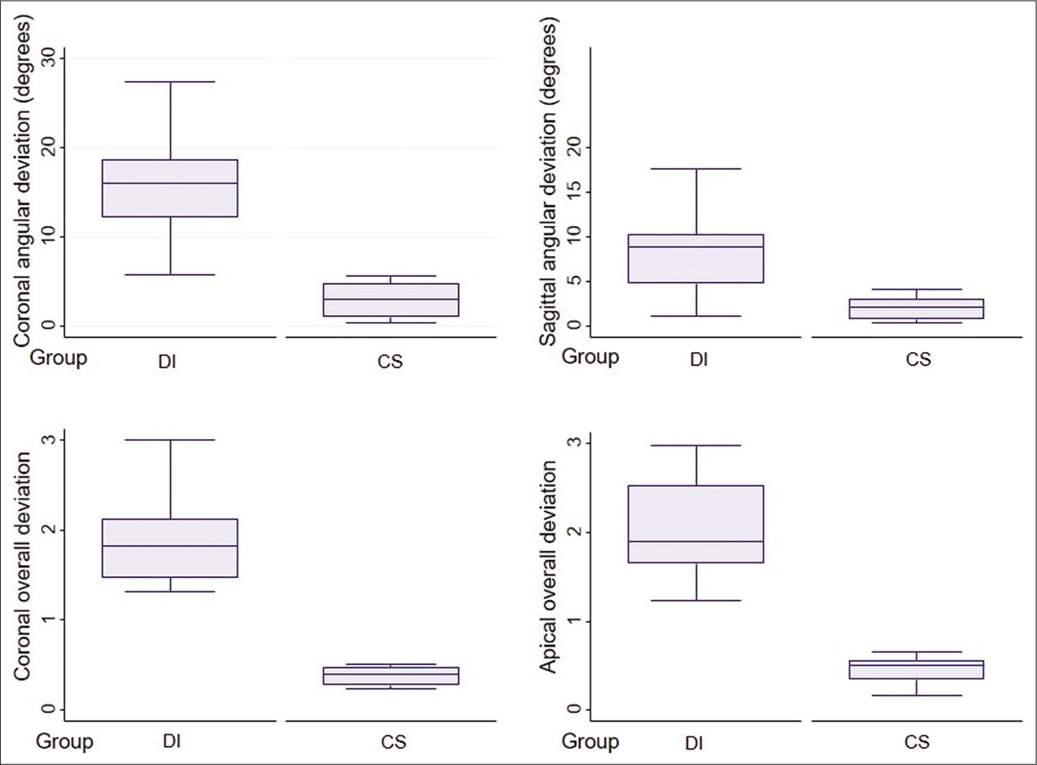
- Box plots presenting coronal angular, sagittal angular, coronal overall and apical overall deviation between direct insertion and CAD/CAM surgical guide groups.
DISCUSSION
Our study found that the DI group had the highest deviations. The orthodontic miniscrews inserted using the DI method had the most deviation because this technique depends on the operator’s senses, and visibility might sometimes be limited. This method can cause unexpected damage to anatomic structures around the teeth, resulting in trauma to the teeth roots. According to Kuroda et al.,[17] contact with or damage to anatomic structures around the roots of teeth occurred in 47.4% of maxillary and 48.3% of mandibular miniscrews placed with a DI method for inter-radicular miniscrew insertion. Lin and Roberts[11] reported that DI causes apical position against the buccal root of the maxillary first molar and obstructs movement to the distal direction. He suggested that to safely direct IZC placement, insertion points between the distal root of maxillary first molar and mesial root of maxillary second molar should be used.
When using the DI method, if the inter-radicular relationship appears clear and the inter-radicular distance seems sufficient in the 2D radiographic images, such as the panoramic or periapical view, miniscrews can be implanted successfully; furthermore, if miniscrews are placed by an experienced orthodontist, the success rate will probably be higher.
The CS group obtained significantly more accurate miniscrew insertion, possibly because the miniscrew driver head was fitted into the driver key, allowing control of the insertion path in 3D and more accurate insertion depth.
A previous study reported that placement position was more accurate when using CAD-CAM surgical guides. Bae et al.[18] used a surgical guide with hand drill diameter 1.2 mm followed by a 1.5 mm diameter miniscrew. The 3D linear distance deviations at the apex had a median of 0.73 mm (range 0.24–2.07 mm). Cassetta et al.[19] employed CAD/CAM surgical guides using the predrill method with palatal miniscrew and found that the deviation at the apex was 1.73 mm (range 0.10–5.41 mm); in contrast, in our study, the driver guide was fitted to the screwdriver head, and the overall apical deviation was 0.50 mm (range 0.16– 0.66 mm). This greater accuracy may be due to the fact that the driver keys in this research were fitted to the driver heads and required less free space than the pre-drilling method.
The protocol of using a driver key for the driver head can be employed with or without a metal sleeve. Metal sleeves within the driver key were found to have mean linear distomesial deviation of 0.42 mm (SD 0.13 mm and range 0.15–0.6 mm) at the tip[20] while our study revealed a deviation of 0.29 mm (range 0.03–0.47 mm) in the same direction. A few errors were detected and deviation rates were similar. The driver key can be built by a 3D printer of any diameter. The advantage of using a driver key without a metal sleeve is that it can be employed with any driver head without the need to prepare a metal sleeve.
Koop et al.[21] reported that the design of driver keys influenced accuracy. Deviations decreased if the distance of the underside of the driver key to the insertion point was made as small as possible. The better the fit, of course, the smaller the deviation. Moreover, deviation increases with longer implant length, larger drill key diameter, and shorter driver key length.[22-24] Our surgical-guide design allowed the entire cylinder of the miniscrew head to be inserted in the driver key to get maximum direction control with the shortest distance to the outer cortex bone at the insertion point. This enables full control in 3D and leads to minimal deviation.
The stability of surgical guides is very important. To reduce placement deviation, there should be adequate surgical guide retention and stability during implantation so that the miniscrews are not dislodged as a result of implantation force during placement. There are many designs, all of which are tooth-borne but differ in tooth covering. The previous reports have used a four-tooth unilateral one[18] and two quadrants or all teeth.[20,25] It is recommended that materials used should be nonflexible.[26] In our design, in which the surgical guides covered three teeth bilaterally from the second premolars to the second molars and were made of hard acrylic, there was sufficient clinical stability.
When 2D images cannot interpret buccal bone width of the desired implantation site or when there are significant anatomic structures nearby such as the maxillary sinus or nerve canal, 3D imaging, such as CBCT, might be necessary for the planning of miniscrew implantation. This imaging can be a valuable tool for fabricating surgical guides to enable successful placement of miniscrews. It is used selectively in patients with miniscrew placement complications, and it yields more accuracy. Placing a miniscrew in limited buccal bone width with inaccurate insertion may result in injury to the roots or cause buccal plate breakage. Furthermore, Lombardo et al.[27] reported that when there are space limitations in the insertion site, surgical guides can help to increase the success rate of miniscrews regardless of operator skill level.
Another study evaluated 3D angular and distance miniscrew deviations by superimposing pre- and post-CBCT images.[20] Reconstructing 3D digital images from computed tomography images is associated with several problems, such as distortion of CBCT image and artifacts caused by metal in the mouth or a beam-hardening effect; however, the use of 3D software utilizing digitally scanned images has been reported to overcome these problems.[28] 3D scans with IOS and fit measurement by landmark points were applied. The 3D digital model from IOS had voxel of 0.02 mm and the deviation was in the lower range, within 0.05–0.07 mm[29] compared to the resolution of 3D from CBCT which had voxel of 0.2 mm. Angular and distance deviation calculated by 3D software is more accurate and also involves less X-ray exposure.
Recent research reported that the type of optical scanning machine used did not affect the accuracy of miniscrew placement, and that intraoral and extraoral scans appeared to result in equal accuracy of implant positioning.[30] There has been some disagreement regarding surgical-guide fabrication performed using different 3D printing techniques. The tested desktop 3D printers were able to produce surgical guides with similar deviations in terms of the final dental implant position, but the DLP printer proved more accurate in terms of deviations at entry point and vertical implant position.[31] Oh et al.[32] reported that the degree of diversion of the driver key did not differ significantly among different 3D printers.
A good surgical guide is one that allows the practitioner to more accurately place the miniscrew in the desired position, with a predefined insertion path and minimal tolerance; however, there are many protocols available in the market. Other parameters such as chair side time, cost-effectiveness, and patient-reported outcomes might be interesting to investigate in future studies. Moreover, the long-term stability of miniscrews also needs to be evaluated in orthodontic patients with miniscrews placed with surgical guides.
CONCLUSION
IZC miniscrew placement using the direct insertion method had the highest deviation, causing unexpected damage to surrounding structures, and leading to mispositioning of the miniscrew head
CAD/CAM IZC miniscrew surgical guides yield the most accurate placement. In cases with anatomical limitations, surgical guides can help to avoid injury to teeth near the insertion site and deliver precise miniscrew head position for better treatment efficiency.
Declaration of patient consent
The authors certify that they have obtained all appropriate patient consent.
Financial support and sponsorship
Nil.
Conflicts of interest
There are no conflicts of interest.
References
- Moderate to severe anterior open-bite cases treated using zygomatic anchorage. J World Fed Orthod. 2012;1:e147-56.
- [CrossRef] [Google Scholar]
- Effectiveness of orthodontic miniscrew implants in anchorage reinforcement during en-masse retraction: A systematic review and meta-analysis. Am J Orthod Dentofacial Orthop. 2017;151:440-55.
- [CrossRef] [PubMed] [Google Scholar]
- Treatment of Class II malocclusion with noncompliance miniscrew implant-supported distalization system. J World Fed Orthod. 2012;1:e79-86.
- [CrossRef] [Google Scholar]
- A computed tomographic image study on the thickness of the infrazygomatic crest of the maxilla and its clinical implications for miniscrew insertion. Am J Orthod Dentofacial Orthop. 2007;131:352-6.
- [CrossRef] [PubMed] [Google Scholar]
- Biomechanics of extra-alveolar mini-implant use in the infrazygomatic crest area for asymmetrical correction of Class II subdivision malocclusion. APOS Trends Orthod. 2018;8:110-8.
- [CrossRef] [Google Scholar]
- Failure rates for stainless steel versus titanium alloy infrazygomatic crest bone screws: A single-center, randomized double-blind clinical trial. Int J Orthod Implantol. 2017;47:96-106.
- [Google Scholar]
- Failure rates of mini-implants placed in the infrazygomatic region. Prog Orthod. 2015;16:31.
- [CrossRef] [PubMed] [Google Scholar]
- CBCT imaging to diagnose and correct the failure of maxillary arch retraction with IZC screw anchorage. Int J Orthod Implantol. 2014;35:4-17.
- [Google Scholar]
- Radiographic and surgical template for placement of orthodontic microimplants in interradicular areas: A technical note. Int J Oral Maxillofac Implants. 2006;21:629-34.
- [Google Scholar]
- Accuracy of miniscrew implant placement with a 3-dimensional surgical guide. J Oral Maxillofac Surg. 2008;66:1245-52.
- [CrossRef] [PubMed] [Google Scholar]
- Accurate pre-surgical determination for self-drilling miniscrew implant placement using surgical guides and cone-beam computed tomography. Eur J Orthod. 2010;32:735-40.
- [CrossRef] [PubMed] [Google Scholar]
- Accuracy and complications using computer-designed stereolithographic surgical guides for oral rehabilitation by means of dental implants: A review of the literature. Clin Implant Dent Relat Res. 2012;14:321-35.
- [CrossRef] [PubMed] [Google Scholar]
- Root proximity is a major factor for screw failure in orthodontic anchorage. Am J Orthod Dentofacial Orthop. 2007;131(Suppl 4):S68-73.
- [CrossRef] [PubMed] [Google Scholar]
- Accuracy of miniscrew surgical guides assessed from cone-beam computed tomography and digital models. Am J Orthod Dentofacial Orthop. 2013;143:893-901.
- [CrossRef] [PubMed] [Google Scholar]
- Palatal orthodontic miniscrew insertion using a CAD-CAM surgical guide: Description of a technique. Int J Oral Maxillofac Surg. 2018;47:1195-8.
- [CrossRef] [PubMed] [Google Scholar]
- Accuracy of surgical positioning of orthodontic miniscrews with a computer-aided design and manufacturing template. Am J Orthod Dentofacial Orthop. 2010;137:728.e1-10. discussion 728-9
- [CrossRef] [PubMed] [Google Scholar]
- Tolerance within the sleeve inserts of different surgical guides for guided implant surgery. Clin Oral Implants Res. 2013;24:630-4.
- [CrossRef] [PubMed] [Google Scholar]
- Accuracy of orthodontic miniscrew implantation guided by stereolithographic surgical stent based on cone-beam CT-derived 3D images. Angle Orthod. 2012;82:284-93.
- [CrossRef] [PubMed] [Google Scholar]
- Accuracy of implant placement with a stereolithographic surgical template. Int J Oral Maxillofac Implants. 2012;27:655-63.
- [Google Scholar]
- Effects of varied dimensions of surgical guides on implant angulations. J Prosthet Dent. 2004;92:463-9.
- [CrossRef] [PubMed] [Google Scholar]
- Precise insertion of orthodontic miniscrews with a stereolithographic surgical guide based on cone beam computed tomography data: A pilot study. Int J Oral Maxillofac Implants. 2011;26:860-5.
- [Google Scholar]
- Accuracy of implant placement based on pre-surgical planning of three-dimensional cone-beam images: A pilot study. J Clin Periodontol. 2007;34:816-21.
- [CrossRef] [PubMed] [Google Scholar]
- Class II treatment by palatal miniscrew-system appliance: A case report. Angle Orthod. 2019;902:305-13.
- [CrossRef] [PubMed] [Google Scholar]
- Original Computer aided support system for safe and accurate implant placement-collaboration with a university originated venture company. Jpn Dent Sci Rev. 2010;46:150-8.
- [CrossRef] [Google Scholar]
- Finish line distinctness and accuracy in 7 intraoral scanners versus conventional impression: An in vitro descriptive comparison. BMC Oral Health. 2018;18:27.
- [CrossRef] [PubMed] [Google Scholar]
- Accuracy of implant position when placed using static computer-assisted implant surgical guides manufactured with two different optical scanning techniques: A randomized clinical trial. Int J Oral Maxillofac Surg. 2019;9:377-83.
- [CrossRef] [PubMed] [Google Scholar]
- Accuracy of surgical guides from 2 different desktop 3D printers for computed tomography-guided surgery. J Prosthet Dent. 2019;121:498-503.
- [CrossRef] [PubMed] [Google Scholar]
- Assessment of metal sleeve-free 3D-printed implant surgical guides. Dent Mater. 2019;35:468-76.
- [CrossRef] [PubMed] [Google Scholar]