Translate this page into:
Simple, quick, and efficient implant placement jig
Address for Correspondence: Dr. Nikhil Narayan Pai, Department of Orthodontics and Dentofacial Orthopedics, SDM College of Dental Sciences and Hospital, Sattur, Dharwad - 580 009. Karnataka, India. E-mail: drnikhilpai@yahoo.com
This article was originally published by Wolters Kluwer and was migrated to Scientific Scholar after the change of Publisher.
Abstract
Implants have become an inherent part of everyday orthodontic practice, but unlike prosthodontic implants, their placement and insertion into narrow interradicular spaces for orthodontic purposes remain a tricky and challenging part to most clinicians. An innovative and clinically useful method has been described here for safe and easy insertion of mini-implants.
Keywords
Implants
insertion
jigs

INTRODUCTION
Mini-implant anchorage system depends on factors related to the clinician’s skills, patient compliance and the screw design itself for its success. Accurate placement of the implants requires meticulous assessment of clinical and radiographical implant insertion site to determine the available bone density and to avoid premature contact with important anatomical structures like roots or the peridontium.
Here, we describe an implant placement jig, which is easy and quick to fabricate chair-side, accurate, cost-effective, reusable, and sterilizable.
FABRICATION OF THE JIG
The jig is fabricated using commonly available 0.014″ ligature wire. The technique involves twisting the ligature wire around the neck of a probe using Mathieu’s needle holder to form a loop [Figure 1]. Next a small horizontal offshoot of the ligature wire is twisted at right angles on either side of the vertical segment of the wire [Figure 2]. The horizontal offshoots given alternately on either side of the vertical segment of the wire after a certain distance help to prevent obscuring the radiographic image at the placement site and also helps to divide the implant insertion region into quadrants for ease of placement [Figure 3]. No special grid is required to check the angulation of the horizontal arms, which can be easily evaluated on the routine arch form template [Figure 4]. The free ends of the jig are then ligated to the brackets of the two adjacent teeth between the roots of which the implant is to be inserted into, with the vertical arm lying in the sulcus between the two teeth [Figure 5].
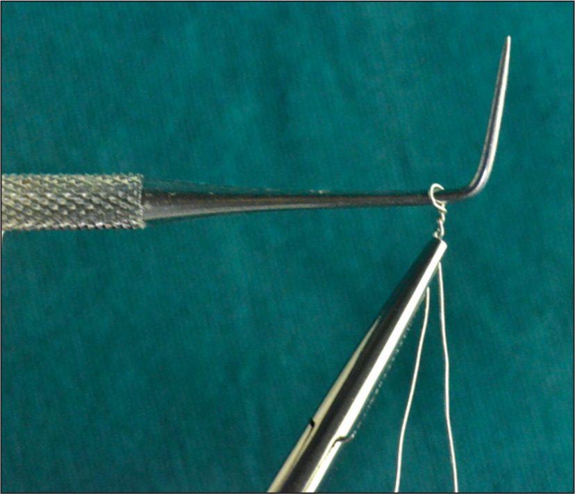
- 0.014″ ligature wire twisted around the neck of a probe using Mathieu’s needle holder to form a loop
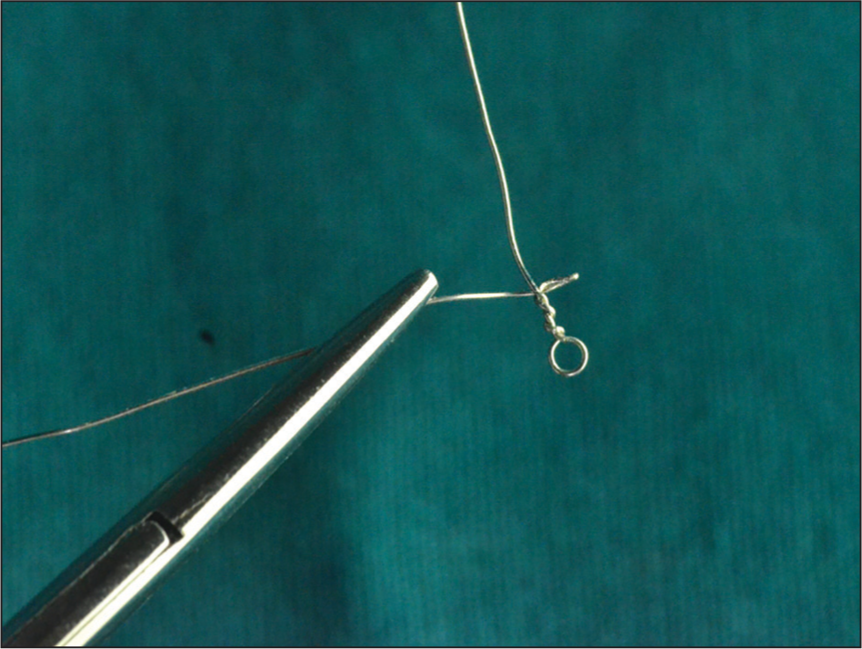
- Small horizontal offshoot of the ligature wire twisted at right angles on either side of the vertical segment of the wire
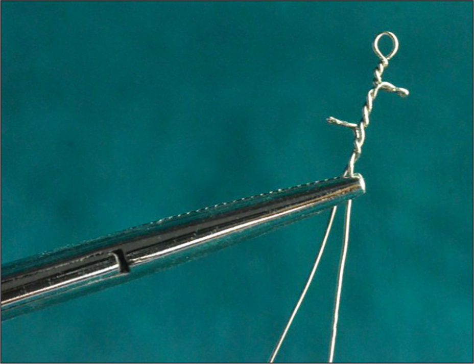
- Horizontal offshoots given alternately on either side of the vertical segment of the wire to divide the implant insertion region into quadrants for ease of placement
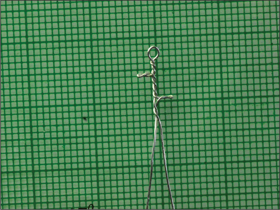
- The 90° angulation of the horizontal arms evaluated on the routine arch form template
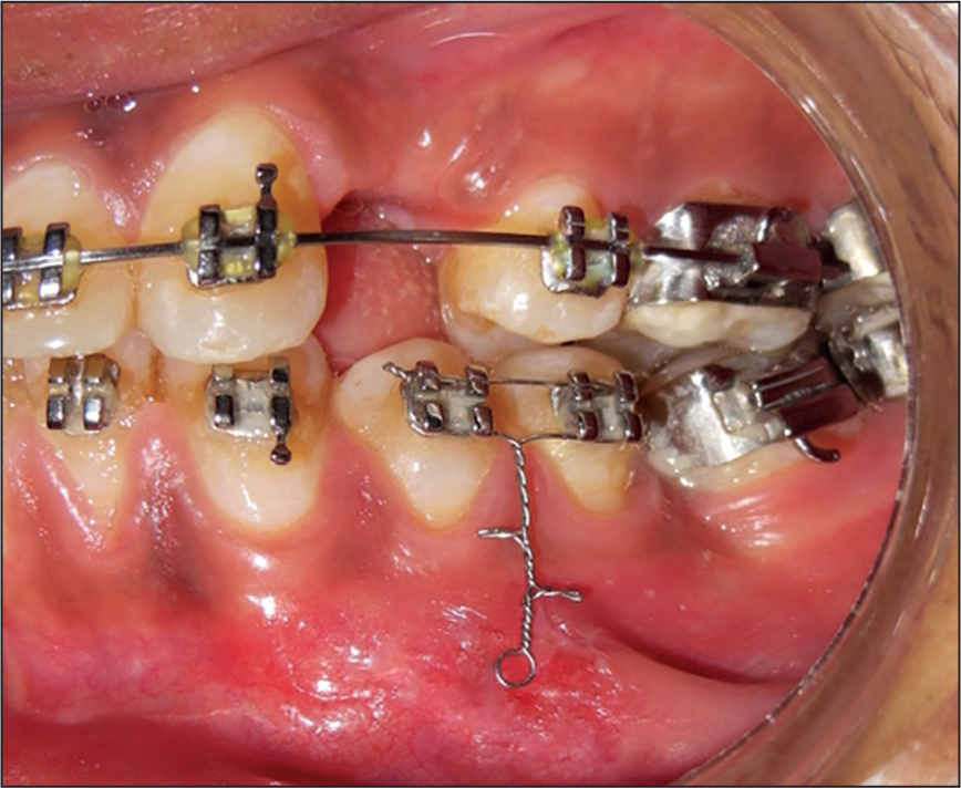
- Intra-oral photograph showing the jig ligated to the brackets of the two adjacent teeth with the vertical arm lying in the sulcus between the two teeth
Next a routine radiograph taken prior to implant placement is obtained [Figure 6]. Here, the site of implant placement is determined, and the quadrant of the jig in which the implant is to be placed is decided. After implant placement into the desired quadrant another regular intraoral periapical (IOPA) is taken to determine the accuracy of the implant insertion [Figure 7]. No additional exposure to X-rays renders this technique to be patient and clinician friendly.
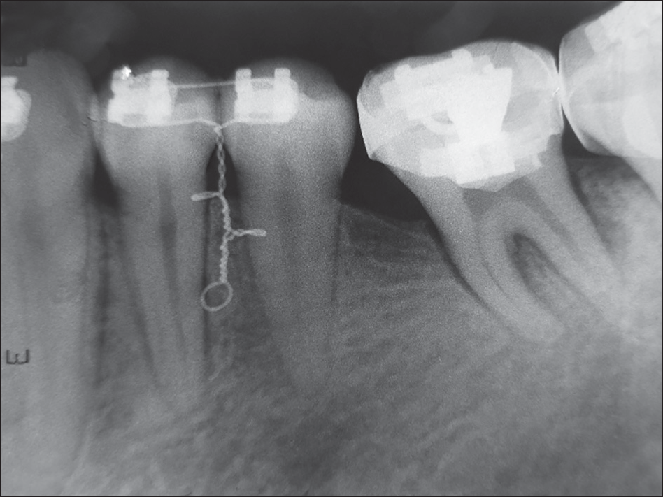
- Radiograph taken prior to implant placement
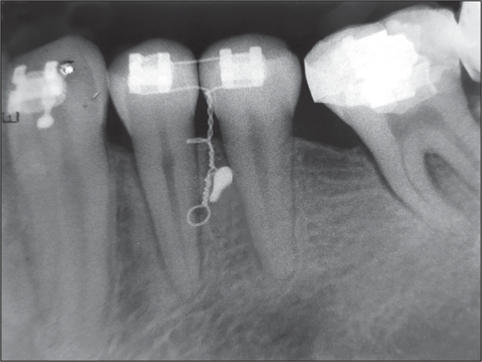
- Radiograph taken after implant placement
Advantages
Simple and easy to fabricate requiring minimal chair-side time.
Autoclavable and hence can be reused for implant placement in another patient.
Cost effective as it makes use of commonly available materials like ligature wire for its fabrication.
Makes use of routine pre- and post-implant placement IOPAs and hence does not expose the patient to any additional radiation.
Since it is fabricated from 0.014″ ligature wire twisted around itself, it is sufficiently rigid.
It consists of all segments at 90° to each other so any displacement in the sulcus can easily be identified and corrected.